Image forming apparatus

a technology of image forming apparatus and forming chamber, which is applied in the direction of electrographic process apparatus, instruments, optics, etc., can solve the problem of increasing the quantity of deposits, and achieve the effect of preventing the deterioration of image quality and enhancing the efficiency of image formation

Inactive Publication Date: 2011-08-02
KONICA MINOLTA BUSINESS TECH INC
View PDF11 Cites 3 Cited by
  • Summary
  • Abstract
  • Description
  • Claims
  • Application Information

AI Technical Summary

Benefits of technology

[0007]In view of these and other issues, an object of the present invention is to provide a high-speed image forming apparatus which is free from occurrence of image noise due to the bleed phenomenon even without providing any contact-and-separation mechanism for the transfer member.
[0009]In this image forming apparatus, part of the image carrier that has been in nip against the transfer member during the stop of the image carrier, i.e., part of the image carrier on which substances that have been bled from the transfer member by the bleed phenomenon are deposited is excluded out of use in image formation until an avoidance sheet count is reached, so that deterioration of image quality due to the deposits can be prevented. Although the deposits are increasingly removed by image forming operations, the quantity of deposits becomes increasingly larger with increasing stop time of the image forming apparatus. Therefore, increasing the avoidance sheet count with increasing stop time makes it possible to minimize the time during which part for use of the image carrier is kept limited. Once the avoidance sheet count is over, the intervals between images may be shortened to improve the image formation speed, thus allowing the image carrier to be used uniformly so that the life can be prolonged.
[0011]Additives and the like are bled from the transfer member in increasingly larger amounts with increasing internal temperature of the apparatus, i.e., atmospheric temperature of the transfer member. Therefore, taking into consideration the temperature during stops makes it possible to correctly calculate the print sheet count required for removal of deposits.
[0013]With a new transfer member, additives and the like are more likely to be bled. Therefore, taking into consideration the cumulated use count of the transfer member makes it possible to more correctly calculate the print sheet count required for removal of deposits.
[0014]According to the above described image forming apparatus, an avoidance sheet count that is a print count to be reached until substances bled from the transfer member and deposited on the image carrier are removed is calculated based on stop time of the image forming apparatus, and keeping the deposit-part out of image formation until the avoidance sheet count is reached. Thus, deterioration of image quality can be prevented, and after the removal of the deposits, the entirety of the image carrier is used, so that the image formation efficiency can be enhanced.

Problems solved by technology

Although the deposits are increasingly removed by image forming operations, the quantity of deposits becomes increasingly larger with increasing stop time of the image forming apparatus.

Method used


Image

  • Image forming apparatus
  • Image forming apparatus
  • Image forming apparatus

Examples


Embodiment Construction

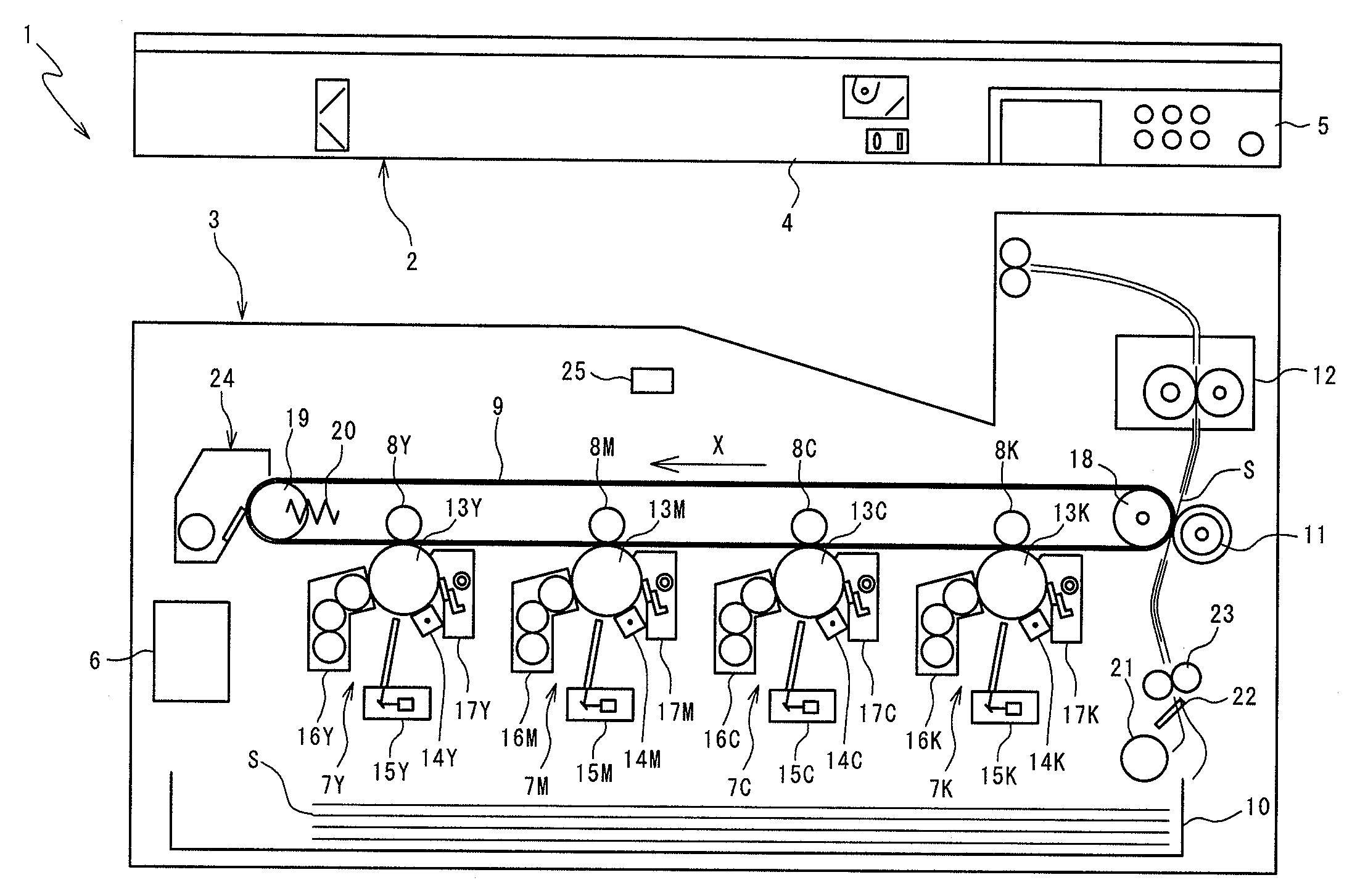
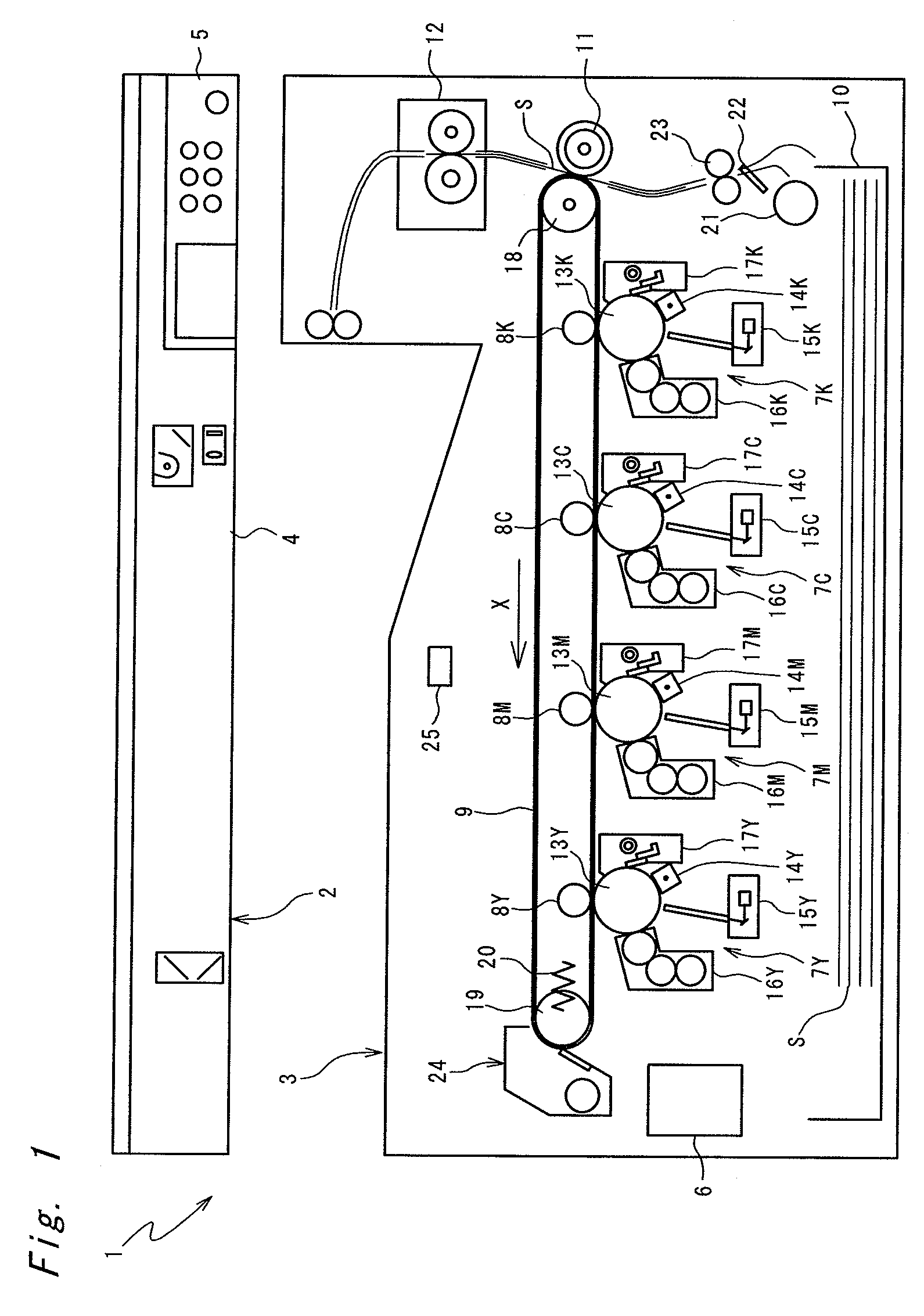
[0026]FIG. 1 shows a schematic construction of a tandem type color digital copier 1 which is one embodiment of the image forming apparatus according to the invention. The color digital copier 1 is composed of an image reader unit 2 for reading an original image, and a printer unit 3 for printing (forming) an image on a recording sheet S based on image data read by the image reader unit 2 or image data received from an unshown computer or the like connected by network.

[0027]The image reader unit 2 includes a known scanner 4 for reading an original image by CCD sensors with three-color separation into red (R), green (G) and blue (B) and further converting the image into an electric signal, and a panel section 5 which is a user interface and which has a display and operation buttons. The printer unit 3 includes a control device 6 for controlling the operation of the copier 1.

[0028]The scanner 4, on reading the original document, creates image data of R, G and B and inputs the resulting...


PUM


Abstract

An image forming apparatus which is free from occurrence of image noise due to the bleed phenomenon even without providing any contact-and-separation mechanism for the transfer member includes a control device which counts stop time elapsing from a stop to a restart of the image carrier, calculates an avoidance sheet count corresponding to the stop time at a restart of the image carrier, and makes a toner image carried on only part of the image carrier that has been out of the nip against the transfer member during the stop of the image carrier until the avoidance sheet count is reached after the restart of the image carrier.

Description

[0001]This application is based on application No. 2008-156313 filed in Japan, the contents of which are hereby incorporated by reference.BACKGROUND OF THE INVENTION[0002]The present invention relates to an image forming apparatus.[0003]In an image forming apparatus in which a toner image is formed on an image carrier such as photoconductor or transfer belt and then transferred onto a recording sheet by electrostatic force of a transfer roller or other transfer member, a top layer of the transfer member is formed of resin foam having both elasticity for slight deformation to ensure a nip (pressure contact) against the image carrier and electrical conductivity for enough chargeability to attract the toner. Such a resin contains low molecular weight materials kept out of chemical reaction in manufacture processes as well as such additives as vulcanizers, softeners or plasticizers. Keeping the transfer member in a prolonged stop as it is nipped against the image carrier causes a bleed ...

Claims


Application Information

Patent Timeline
Patent Type & Authority Patents(United States)
IPC IPC(8): G03G15/00
CPCG03G15/1605G03G2215/00772G03G2215/00776G03G2215/0132G03G2215/1661
Inventor HIROI, TOSHIAKI
Owner KONICA MINOLTA BUSINESS TECH INC
Why Eureka
Try Eureka