Curved positioning and insertion instrument for inserting a guide wire into the femur

a positioning and insertion instrument technology, applied in the direction of instruments, printing, prosthesis, etc., can solve the problem of more difficult visual estimation of a certain angle than a parallelism

Inactive Publication Date: 2011-08-30
SYNTHES USA
View PDF23 Cites 5 Cited by
  • Summary
  • Abstract
  • Description
  • Claims
  • Application Information

AI Technical Summary

Benefits of technology

[0010]In order to achieve the object, the inventor now presents a novel positioning and insertion instrument which comprises a handle which is arranged by means of a retaining arm on a curved guide tube. At the end thereof there is a positioning hook with, if appropriate, a guide bore which is oriented at an angle of 6°-30°, preferably 7°-20°, in particular about 8°, relative to the guide tube. In addition to this bore, various correction bores are present, according to an improved further development. Furthermore, a T-handle is required when the instrument according to the invention is used. The invention thus makes it possible to insert at least one guide wire which subsequently guides an opening drill. Instead of a T-handle or a motorized drilling or tapping drive, it is also possible to provide an impact head so that the guide wire can be hammered in.

Problems solved by technology

This procedure is carried out because it is more difficult to estimate a certain angle visually than a parallelism.

Method used


Image

  • Curved positioning and insertion instrument for inserting a guide wire into the femur
  • Curved positioning and insertion instrument for inserting a guide wire into the femur
  • Curved positioning and insertion instrument for inserting a guide wire into the femur

Examples


Embodiment Construction

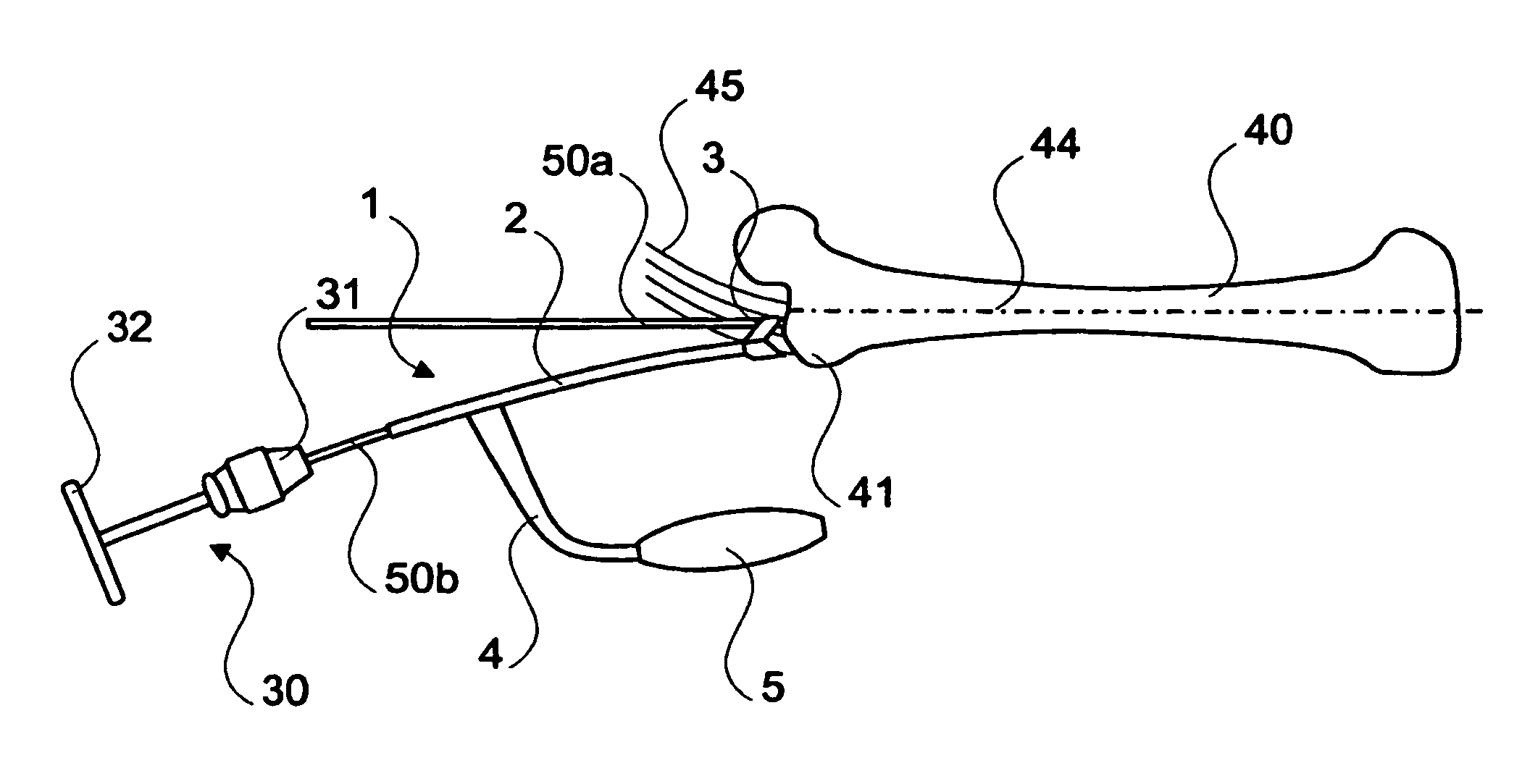
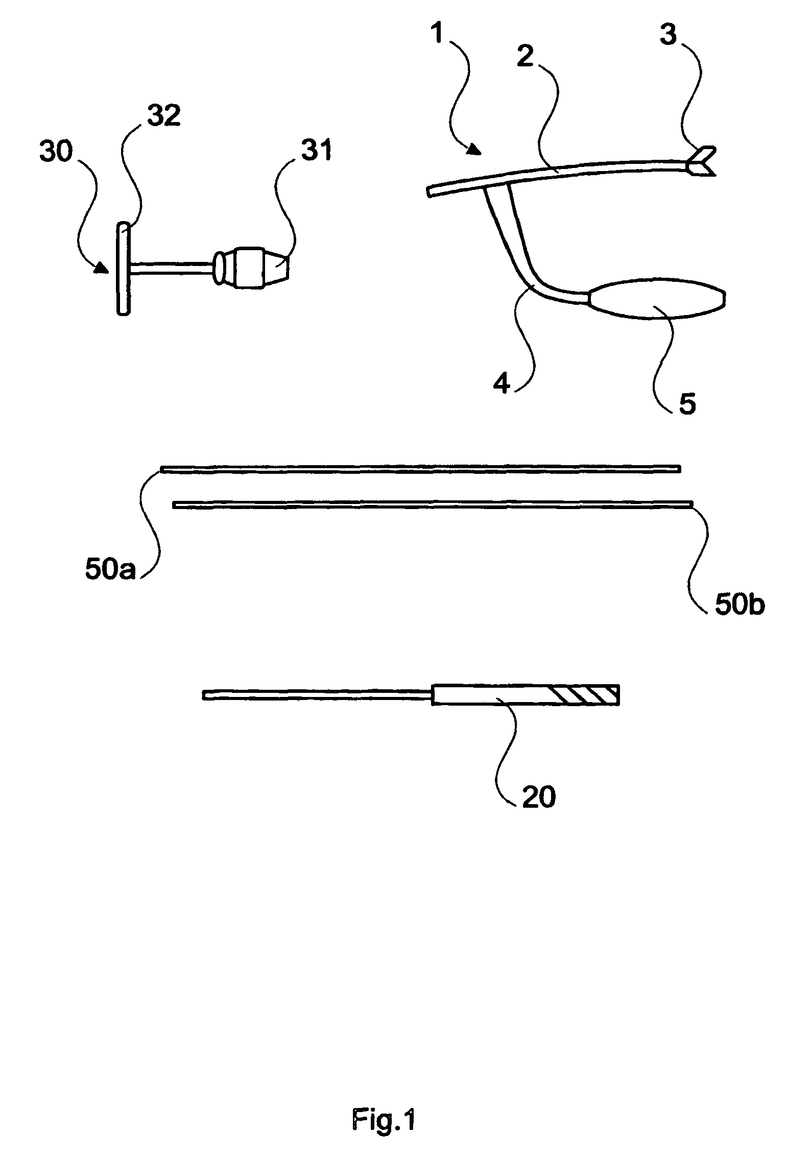
[0041]FIG. 1 shows the individual components which as a rule are required in using the instrument according to the invention. The positioning and insertion instrument 1 consists of a curved guide tube 2, at the distal end of which a positioning hook 3 is arranged. The curvature of the guide tube 2 describes a radius of about 300 to 800 mm, preferably 500 to 700 mm, in particular about 600 mm. The positioning hook 3 is formed in such a way that it is retained on the tip of the greater trochanter and the medial muscle. In the region of the proximal end of the guide tube 2, mounted approximately perpendicularly thereto, is a retaining arm 4 which then curves in order to run approximately parallel to the guide tube 2. A handle 5, the longitudinal axis of which is approximately parallel to a tangent to the guide tube 2 in the region of the positioning hook 3, is present at the end of the retaining arm 4. Furthermore, FIG. 1 shows two guide wires 50 which are such that they can be inserte...


PUM


Abstract

A curved positioning and insertion instrument for inserting a guide wire into the femur has a curved guide tube with a distal end to be placed on the trochanter and / or the medial muscle and a proximal end for inserting a guide wire. The instrument also has a holding arm that links the guide tube to a handle. A positioning hook fitted with at least one correction bore for receiving the guide wire or another guide wire is arranged at the distal end of the guide tube. This structure makes it possible to easily insert further or additional guide wires relative to a reference guide wire.

Description

RELATED APPLICATION DATA[0001]The present application is a continuation of the U.S. National Stage designation of co-pending International Patent Application No. PCT / IB2004 / 000624, filed Mar. 8, 2004, which claims priority to Swiss Patent Application Nos. 01395 / 03, filed Aug. 13, 2003, and 00026 / 04, filed Dec. 23, 2003, the entire content of which are expressly incorporated herein by reference thereto.FIELD OF THE INVENTION[0002]The invention relates to a curved positioning and insertion instrument for inserting a guide wire into the femur for precise bone opening.BACKGROUND OF THE INVENTION[0003]Precise bone opening requires a reliable reference in position and direction which a surgeon with a drill or cutter can use as a guide. It is known that guide wires which are inserted (drilled or tapped) into the femur prior to drilling in order to guide the drill safely are used for this purpose.[0004]U.S. Pat. No. 6,074,392 describes such a curved positioning and insertion instrument for ...

Claims


Application Information

Patent Timeline
Patent Type & Authority Patents(United States)
IPC IPC(8): B65H57/00A61B17/16A61B17/17A61B17/72
CPCA61B17/1697A61B17/1717A61B17/7208A61B17/8897A61B17/72A61B17/68A61B17/17A61B17/16
Inventor KAUP, THOMASFERNANDEZ DELL'OCA, ALBERTO
Owner SYNTHES USA
Why Eureka
Try Eureka