Al technical title is built by PatSnap Al team. It summarizes the technical point description of the patent document.
a surgical device and stapling technology, applied in the field of surgical devices, can solve the problems of difficult maneuverability of devices, conventional surgical devices, difficult maneuverability, etc., and achieve the effect of comfort, and improving the patient's comfor
Inactive Publication Date: 2011-09-13
TYCO HEALTHCARE GRP LP
View PDF600 Cites 1621 Cited by
Summary
Abstract
Description
Claims
Application Information
AI Technical Summary
This helps you quickly interpret patents by identifying the three key elements:
Problems solved by technology
Method used
Benefits of technology
[0011]According to one example embodiment of the present invention, a first drive socket is configured to couple to one end of a first rotatable drive shaft, arranged at an angle, e.g., perpendicular, to the plane of the first and second jaws of an electro-mechanical driver, wherein the electro-mechanical driver is configured to rotate the first rotatable drive shaft. The first rotatable drive shaft is rotated in a first direction to effect opening of the jaws and is rotated in a second direction opposite to the first direction to effect closing of the jaws. The first driver may include, for example, a pair of spur gears, a worm and a worm gear in turning and gearing relationship with each other. The first driver may also include an externally-threaded screw fixedly connected at one end to one of the worm gears and in engagement with an internally-threaded bore of the second jaw, the rotation of the gears thereby causing relative movement of the first jaw and the second jaw.
Problems solved by technology
One problem with the foregoing surgical devices is that the devices may be difficult to maneuver.
Conventional surgical devices, such as those illustrated in FIGS. 1(a) and 1(b), are difficult to maneuver, especially inside the patient's body.
Method used
Image
Click on the blue label to locate the original text in one second.
Reading with bidirectional positioning of images and text.
Examples
Embodiment Construction
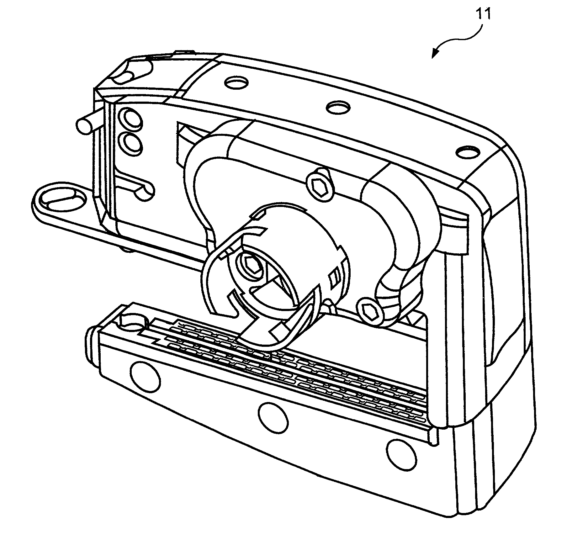
[0042]One example embodiment of a surgical device 11 according to the present invention is illustrated in FIGS. 3 to 7. Referring to FIGS. 3 and 4, an example embodiment of the surgical device 11, e.g., a clamping, cutting and stapling device, is illustrated. In this example embodiment, the surgical device 11 includes a parallel separating jaw system having a second jaw 50 in opposite correspondence to a first jaw 80. A first end 50a of second jaw 50 is mechanically coupled to a first end 80a of first jaw 80. The opposing jaws 50 and 80 may remain parallel relative to each other. Alternatively, opposing jaws 50 and 80 may open and close in scissor-like fashion, wherein the first ends 50a and 80a of the second jaw 50 and the first jaw 80 are mechanically connected by a hinge or other rotational element such that the first jaw 80 is rotatably coupled to the second jaw 50.
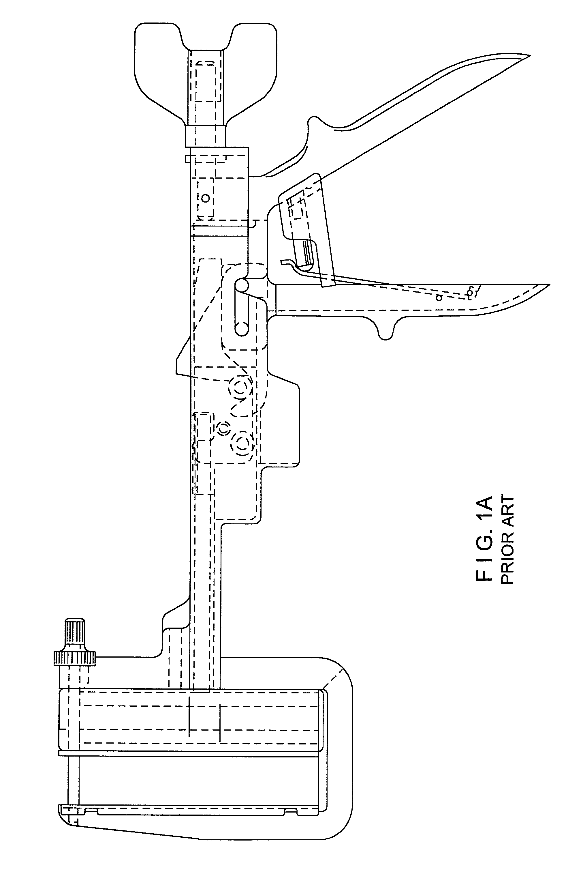
[0043]FIG. 3 illustrates the surgical device 11 in an open position, wherein the second jaw 50 and the first jaw 80...
PUM
Property
Measurement
Unit
time
aaaaa
aaaaa
thickness
aaaaa
aaaaa
thickness
aaaaa
aaaaa
Abstract
A surgical device includes a first jaw and a second jaw in opposed correspondence with the first jaw. A first driver is configured to cause relative movement of the first jaw and the second jaw in a plane. The first driver is configured to engage a drive shaft rotatable about a rotation axis arranged in non-parallel, e.g., perpendicular, correspondence to the plane. The device may also include a surgical member, e.g., a cutting and stapling element, disposed within the first jaw. A second driver is configured to cause relative movement of the surgical member in a direction parallel to the plane. The second driver is configured to engage a drive shaft rotatable about a rotation axis arranged in non-parallel correspondence to the plane.
Description
CROSS-REFERENCE TO RELATED APPLICATIONS[0001]The present application claims the benefit of U.S. patent application Ser. No. 60 / 346,656, filed on Jan. 8, 2002, which is expressly incorporated herein by reference in its entirety.[0002]The present application is related to U.S. patent application Ser. No. 09 / 510,923, filed on Feb. 22, 2000, U.S. patent application Ser. No. 09 / 723,715, filed on Nov. 28, 2000, U.S. patent application Ser. No. 09 / 836,781, filed on Apr. 17, 2001, U.S. patent application Ser. No. 09 / 887,789, filed on Jun. 22, 2001, and U.S. patent application Ser. No. 60 / 337,544, filed on Dec. 4, 2001, each of which is expressly incorporated herein by reference in its entirety.FIELD OF THE INVENTION[0003]The present invention relates to a surgical device. More specifically, the present invention relates to a clamping, cutting and stapling device for clamping, cutting and stapling tissue.BACKGROUND INFORMATION[0004]The literature is replete with descriptions of surgical devi...
Claims
Application Information
Patent Timeline
Application Date:The date an application was filed.
Publication Date:The date a patent or application was officially published.
First Publication Date:The earliest publication date of a patent with the same application number.
Issue Date:Publication date of the patent grant document.
PCT Entry Date:The Entry date of PCT National Phase.
Estimated Expiry Date:The statutory expiry date of a patent right according to the Patent Law, and it is the longest term of protection that the patent right can achieve without the termination of the patent right due to other reasons(Term extension factor has been taken into account ).
Invalid Date:Actual expiry date is based on effective date or publication date of legal transaction data of invalid patent.