Wedge lock anchor mount

a technology of anchor mount and lock rod, which is applied in the direction of coupling, rod connection, machine support, etc., can solve the problems of inability to provide efficient and reliable mounting apparatus for pipe and tube hole plug devices, inability to guarantee the security of accessory devices, and general failure of known lengthwise locking mechanisms

Active Publication Date: 2011-09-20
CARNEVALI JEFFREY D
View PDF12 Cites 34 Cited by
  • Summary
  • Abstract
  • Description
  • Claims
  • Application Information

AI Technical Summary

Problems solved by technology

However, such known lengthwise locking mechanisms in general tend to fail when any portion of the telescoping pole is rotated relative to another portion thereof.
Furthermore, it is known to provide mounting platforms that can accommodate the limited available space normally found in a vehicle for mounting add-on equipment.
However, security of the accessory device remains uncertain.
However, known pipe and tube hole plug apparatus are limited in their ability to provide efficient and reliable mounting apparatus external of the plugged pipe or tube.

Method used


Image

  • Wedge lock anchor mount
  • Wedge lock anchor mount
  • Wedge lock anchor mount

Examples


Embodiment Construction

[0040]In the Figures, like numerals indicate like elements.

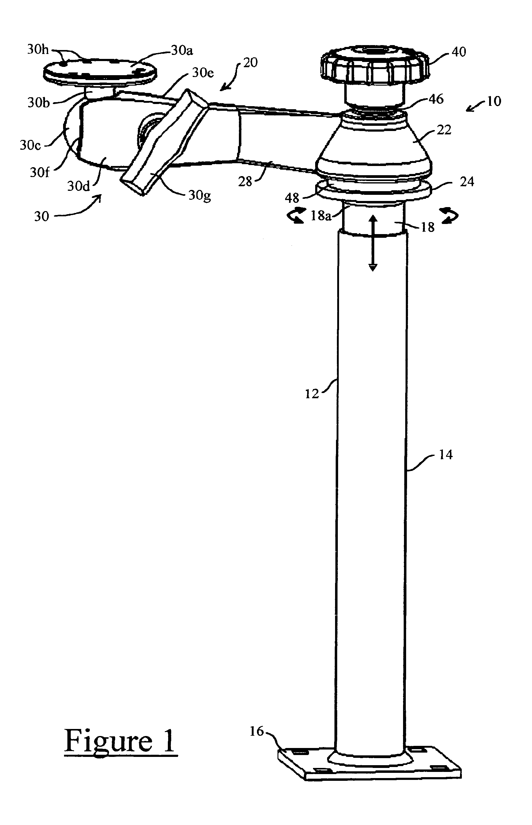
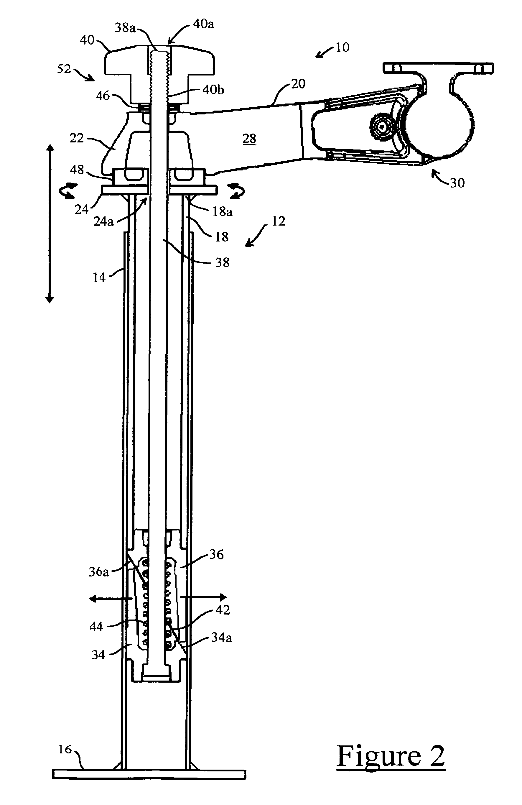
[0041]FIG. 1 illustrates the present invention by example and without limitation embodied as a telescoping pole mount 10 having at its core a telescoping pole 12 formed of an outer female tube 14 standing on a base plate 16, and an inner male tube 18 sized to slide lengthwise within the female tube 14, as indicated by the straight arrows, to different lengthwise relative positions. The relative positions of the female and male tubes 14, 18 of the telescoping pole 12 are arbitrary and are optionally reversed in a device that practices the present invention within the scope and intent of the present invention. A rotatable apparatus or mechanical arm 20 is mounted on the male tube 18 external to the female tube 14 and is rotatable about the telescoping pole 12, as indicated by the curved arrows, without unlocking the female and male tubes 14, 18.

[0042]According to embodiment, the rotatable mechanical arm 20 includes a hub 22 th...


PUM


Abstract

An anchor mount formed of: a mounting device; a laterally expandable locking mechanism coupled to the base of the mounting device, the laterally expandable locking mechanism including first and second cooperating wedges, the first wedge being coupled to the base of the mounting device, and the second wedge being movable along an inclined plane of mutual contact with the first wedge and substantially laterally expandable relative thereto; a reaction surface fixed relative to the first wedge; an actuator having an actuation surface that is positioned adjacent to the reaction surface and movable relative thereto; and the second wedge being responsive to motion of the actuation surface of the actuator relative to the reaction surface for moving along the inclined plane of mutual contact with the first wedge and substantially laterally expanding relative thereto.

Description

[0001]This application is a Continuation-in-part and claims priority benefit of U.S. patent application Ser. No. 11 / 118,734 filed in the name of Jeffrey D. Carnevali on Apr. 29, 2005 now U.S. Pat. No. 7,802,768, the complete disclosures of which are both incorporated herein by reference.FIELD OF THE INVENTION[0002]The present invention relates to trays for holding portable devices, and in particular to locking trays for holding portable electronic devices, including lap top computers and other similarly sized electronics devices.BACKGROUND OF THE INVENTION[0003]Lengthwise locking mechanisms for telescoping pole devices are generally well known. However, such known lengthwise locking mechanisms in general tend to fail when any portion of the telescoping pole is rotated relative to another portion thereof. Subsequently, the telescoping portions of the pole become unlocked, and slide one within the other, thereby releasing the locking mechanism.[0004]Furthermore, it is known to provide...

Claims


Application Information

Patent Timeline
Patent Type & Authority Patents(United States)
IPC IPC(8): F16M11/00F16B2/14
CPCF16B7/14F16M11/28F16M11/14F16M11/2014F16M13/00F16B13/0891Y10T403/7056F16M2200/024F16M2200/027F16M2200/068Y10T403/7075Y10T403/7069F16B7/1418
Inventor CARNEVALI, JEFFREY D.
Owner CARNEVALI JEFFREY D
Why Eureka
Try Eureka