
Insulated panels

a technology of insulated glass and door panels, applied in the direction of defrosting, building repairs, domestic cooling apparatus, etc., can solve the problems of increasing the cost of doors and fridges/freezers overall, requiring additional circuitry, and complicating the construction of door panels and door frames, so as to reduce or eliminate condensation and improve the structure

Inactive Publication Date: 2011-09-27
MCKINLAY KING JULIAN
View PDF38 Cites 14 Cited by
  • Summary
  • Abstract
  • Description
  • Claims
  • Application Information

AI Technical Summary

Benefits of technology

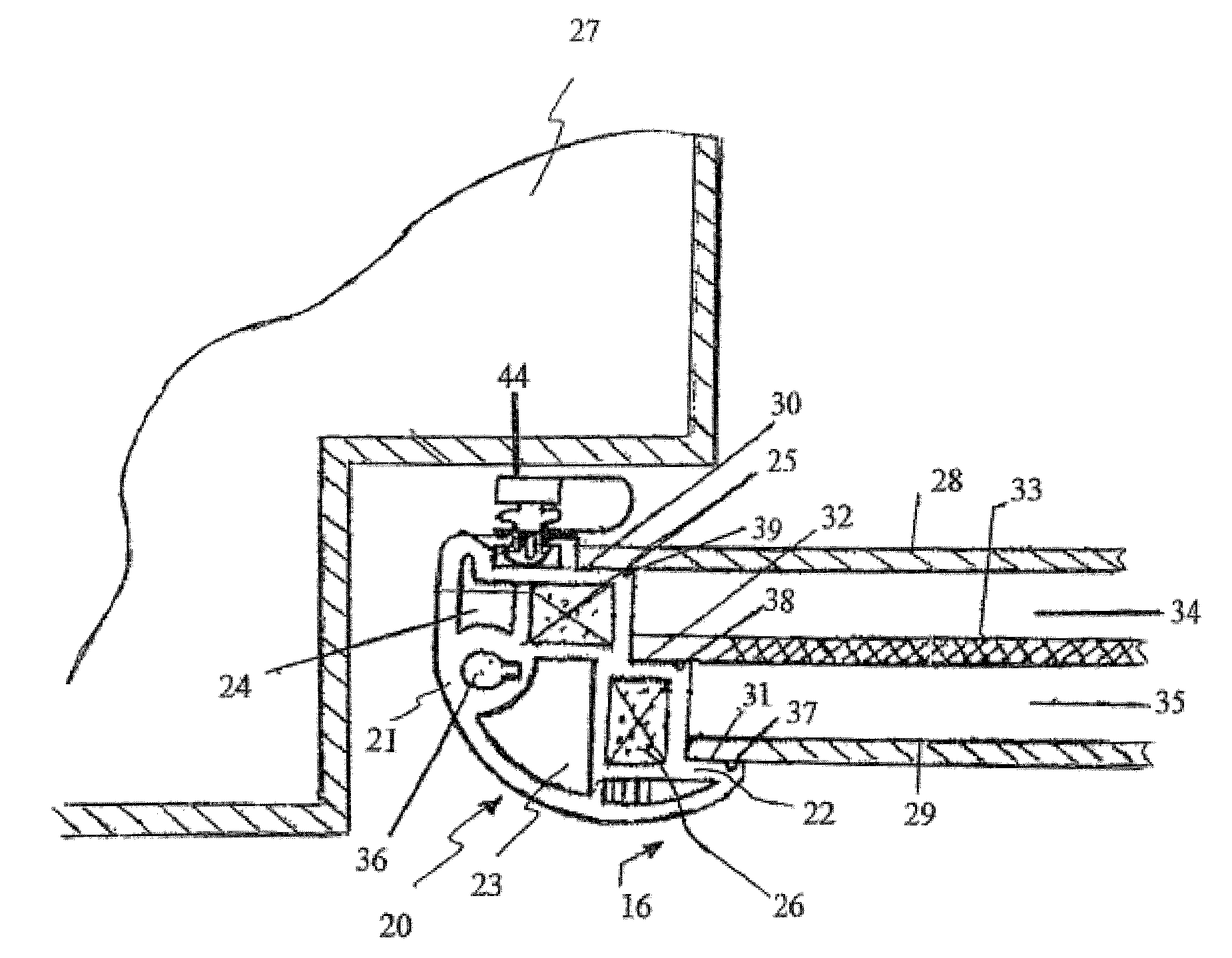
"The present invention provides improvements in insulating glass doors of refrigerators and freezers by reducing or eliminating condensation on the glass surfaces and door-frame. This is achieved without the need for electrical heating, which reduces operating and maintenance costs. The invention also provides an alternative to the known methods of insulating double / triple-glazed windows and construction of glazed fridge / freezer doors. The invention provides a novel insulating panel with a frame and walls that create enclosed spaces between them to prevent moisture from accumulating on the walls. The frame has a cascading series of mounting surfaces that provide the frame with a multi-layered series of spaces in which the walls are insulated. The walls are affixed to the mounting surfaces using a rigid or semi-rigid adhesive and may have recesses to trap any excess adhesive. The enclosed spaces are sealed and filled with air, argon gas, foam, or other insulating material. The invention also provides a gasket-retaining groove for a magnetized flexible sealing gasket to create an airtight seal between the panel and an article."

Problems solved by technology

The heating apparatuses required to maintain the door panels and door-frame at an optimum temperature add to the cost of the doors and fridge / freezer overall, complicate the construction of the door panels and door-frame, require additional circuitry, and add to the running costs of the fridge / freezer as well as the air conditioning generally employed.

Method used


Image

  • Insulated panels
  • Insulated panels
  • Insulated panels

Examples


Embodiment Construction

[0044]The present invention will now be described in more detail according to preferred but non-limiting embodiment and with reference to the accompanying illustrations wherein:

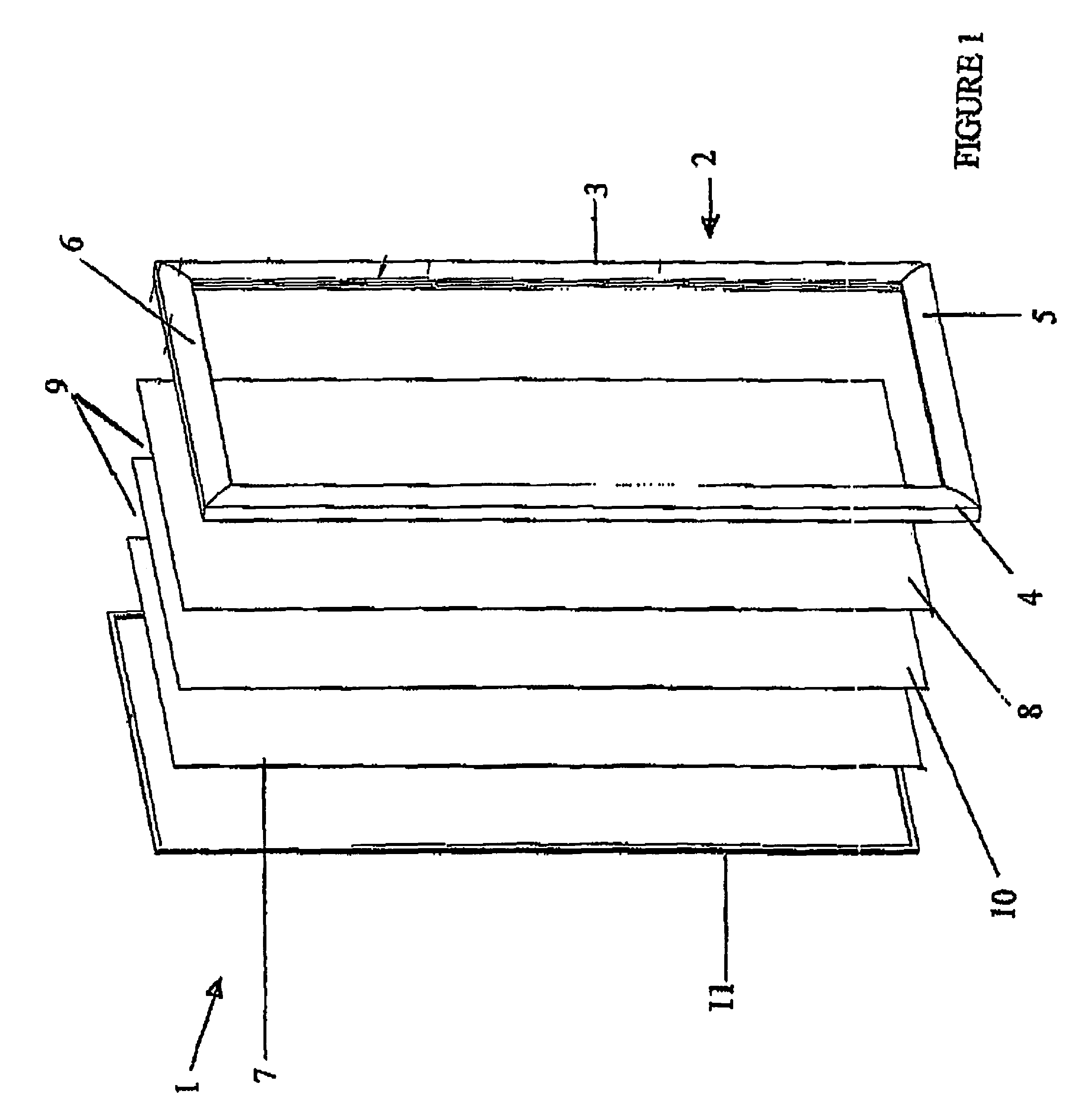
[0045]FIG. 1 shows an exploded perspective view of a door panel according to one embodiment;

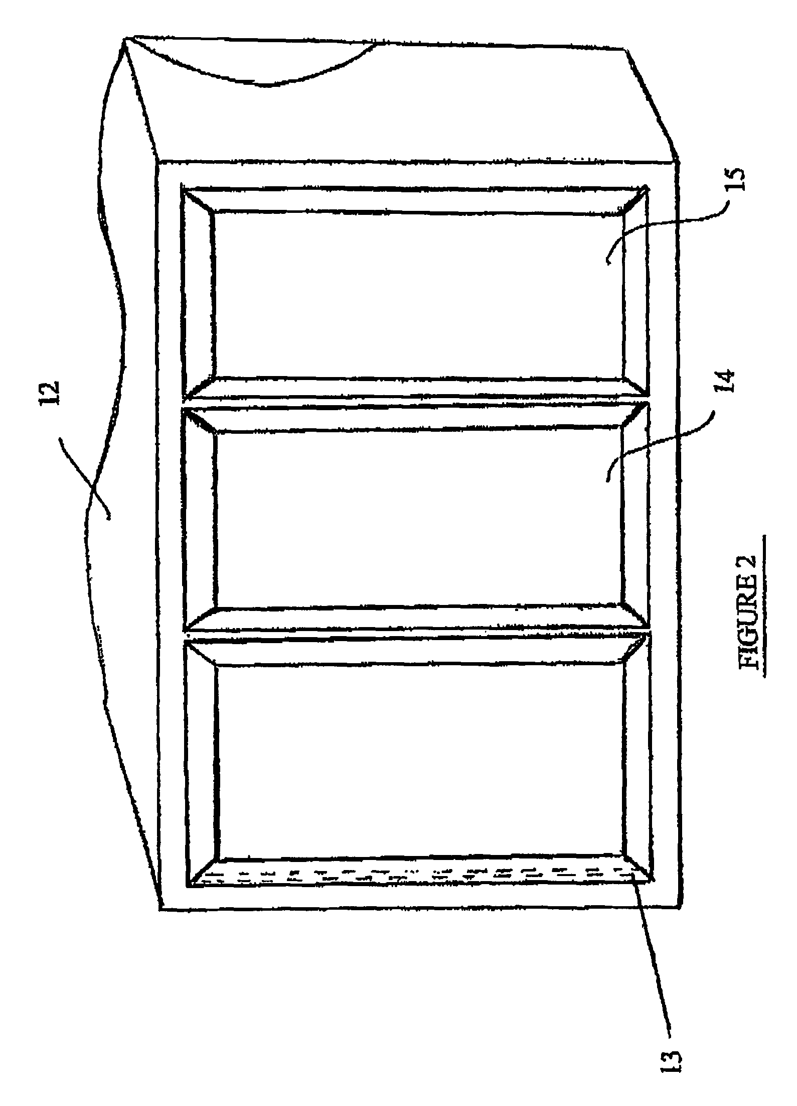
[0046]FIG. 2 shows a front elevation of a refrigeration unit having three doors according to one embodiment;

[0047]FIG. 3 is an enlarged cross sectional view of an abbreviated frame extrusion including fitted glass panels and an intermediate insulating panel;

[0048]FIG. 4 is a cross sectional diagram of a frame extrusion for an insulated glass door according to one embodiment;

[0049]FIG. 5 shows a part elevation view of a door panel frame from a front view;

[0050]FIG. 6 shows a part elevation view of a door panel frame from a rear view;

[0051]FIG. 7 shows an isometric view of a section of a panel with panes fitted according to a preferred embodiment;

[0052]FIG. 8 shows an enlarged cross sectional view of an extrusion used in...


PUM

PropertyMeasurementUnit
planar insulatingaaaaaaaaaa
mechanicalaaaaaaaaaa
insulatingaaaaaaaaaa

Abstract

A panel comprising: a frame member (70) defining a periphery of said panel; a first wall (77) retained by the frame (70) and a second wall (79) opposing said first wall (77) and together with the first wall (77) defining an internal space (73, 74) of the panel; the panel further comprising at least one intermediate wall (78) disposed in said internal space intermediate the first (77) and second walls (79) and which creates a first space (73) in said internal space between said intermediate wall (78) and said first wall (77) and a second space (74) in said internal space between said intermediate wall (78) and said second wall (79); characterized in that the frame includes respective abutment surfaces (80, 81, 82) which receive and retain respective first, second and intermediate walls wherein; the intermediate wall (78) insulates said first wall (77) from said second wall (79).

Description

BACKGROUND[0001]The present invention relates to improvements in insulated glass door and window structures and more particularly relates to an apparatus and method for eliminating or reducing condensation on the external face of such glass doors and the internal face of window structures. More particularly the present invention relates to improvements in the structure of insulated glass door / window structures such as are used in connection with insulated glazed windows (for use in both thermal and sound insulation applications) and refrigeration, and particularly in industrial and commercial refrigeration. The invention also relates to improvements in the economics of manufacture of insulated glass doors and windows. Although the invention will primarily be described with reference to its application in glass doors and particularly triple glazed doors used in such applications as refrigeration, it will be appreciated by persons skilled in the art that the invention has applications...

Claims


Application Information

Patent Timeline
Patent Type & Authority Patents(United States)
IPC IPC(8): E06B7/00E06B7/12E06B3/24F25D21/04F25D23/02
CPCE06B3/22E06B3/56E06B3/64E06B3/6617E06B3/6775E06B3/9608F25D21/04F25D23/02E04B1/80E04C2/26
Inventor MCKINLAY, ROSS CAMPBELLPICKFORD, MURRAY CHRISTIAN
Owner MCKINLAY KING JULIAN
Learn More