Anchor assembly

a technology of anchors and assemblies, applied in the field of anchor assemblies, can solve problems such as more difficul

Inactive Publication Date: 2011-09-27
D B IND
View PDF10 Cites 56 Cited by
  • Summary
  • Abstract
  • Description
  • Claims
  • Application Information

AI Technical Summary

Problems solved by technology

However, this may be more difficult when workers are performing tasks such as building construction because the anchorage members are often difficult to secure and may interfere with the workers' tasks.

Method used


Image

  • Anchor assembly
  • Anchor assembly
  • Anchor assembly

Examples


Embodiment Construction

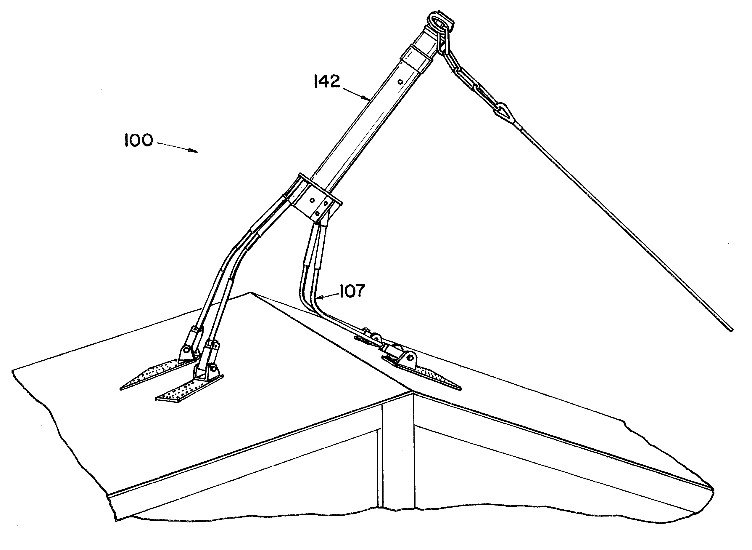
[0019]An anchor assembly constructed according to the principles of the present invention is designated by the numeral 100 in the drawings. Another embodiment anchor assembly constructed according to the principles of the present invention is designated by the numeral 100′ in the drawings.

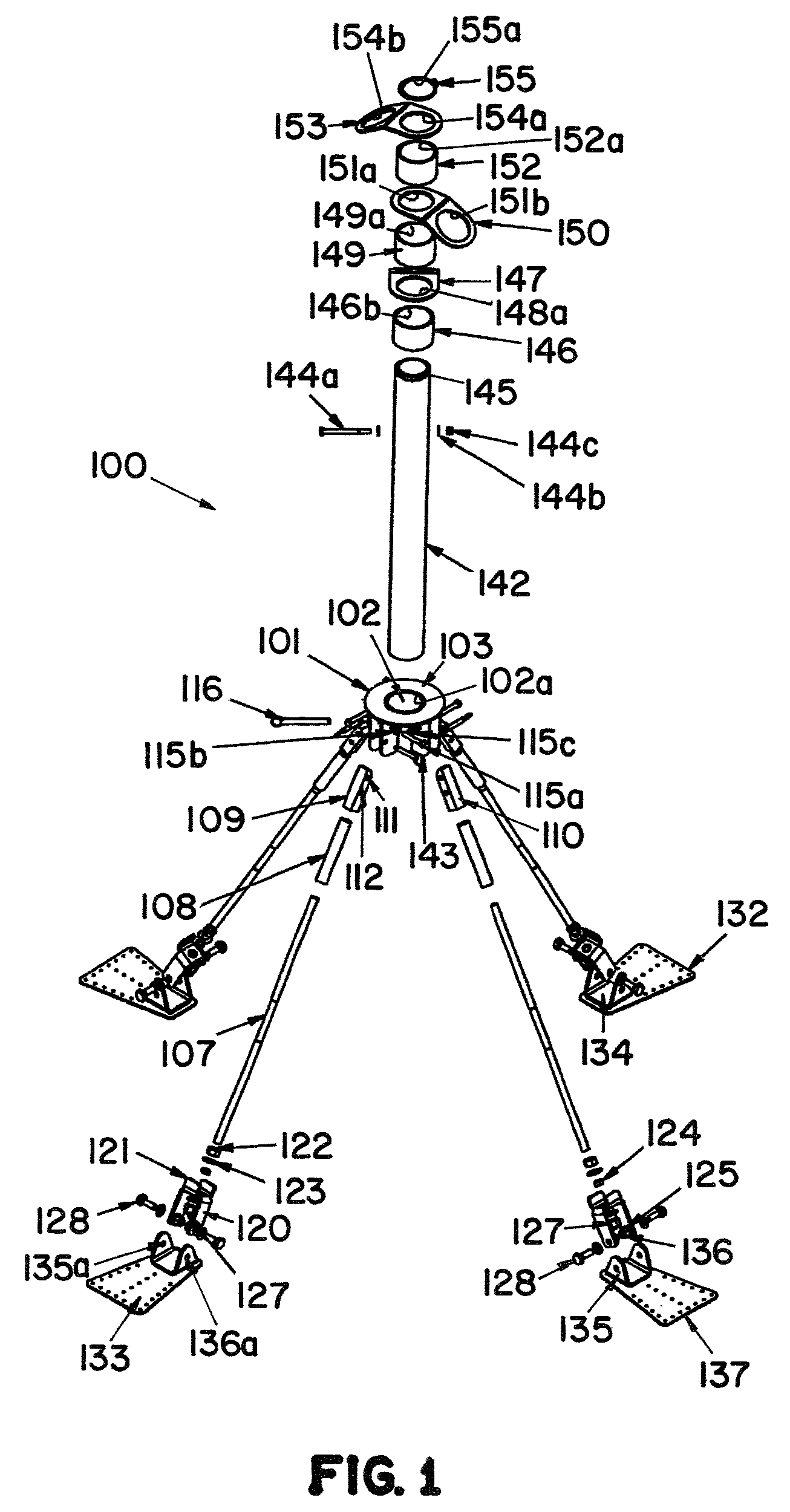
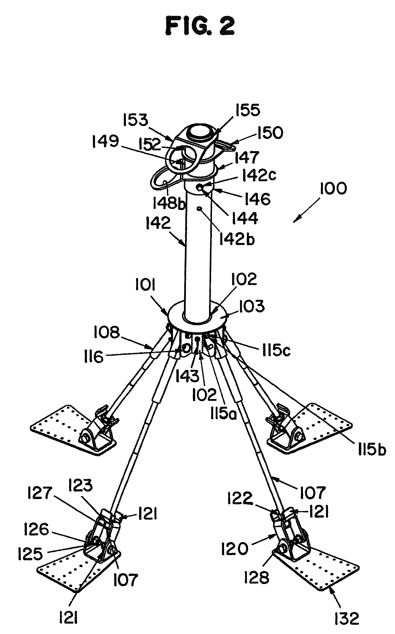
[0020]The anchor assembly 100 includes a base 101 to which legs 107 and connectors 147, 150, and 153 are operatively connected. Although four legs 107 are shown and described, it is recognized that at least three legs should preferably be used. Further, although three connectors 147, 150, and 153 are shown and described, it is recognized that one or more connectors may be used.

[0021]The base 101 includes a cylindrical member 102 having a bore 102a extending longitudinally through the cylindrical member 102 and a flange 103 extending outward from the top of the cylindrical member 102. Mounting brackets 104 extend outward from the sides of the cylindrical member 102 and downward from the flange 103 t...


PUM


Abstract

An anchor assembly includes a base to which at least one connector and three legs are operatively connected. The connector provides an anchorage point for connection to a lifeline. The legs are secured to a support structure. The legs are reinforced proximate the base and when a force is exerted on the at least one connector by the lifeline, the legs bend proximate the support structure thus placing a shear load on the legs proximate the support structure.

Description

[0001]This application claims the benefit of U.S. Provisional Patent Application Ser. No. 60 / 856,608, filed Nov. 3, 2006.FIELD OF THE INVENTION[0002]The present invention relates to an anchor assembly for anchoring fall protection and fall arrest safety apparatus to a support structure.BACKGROUND OF THE INVENTION[0003]Various occupations place people in precarious positions at relatively dangerous heights, thereby creating a need for fall protection and fall arrest safety apparatus. Among other things, such apparatus may include a lifeline operatively connected to an anchorage member secured to a support structure, and a person working in proximity to the anchorage member is operatively connected to the lifeline. Obviously, the lifeline and the anchorage member must be secure enough to provide fall protection for workers during movement proximate the anchorage member. However, this may be more difficult when workers are performing tasks such as building construction because the anch...

Claims


Application Information

Patent Timeline
Patent Type & Authority Patents(United States)
IPC IPC(8): A62B35/00A62B99/00
CPCA62B1/04A62B35/0068E04G21/3261E04H12/2238E04G21/3276E04G21/329
Inventor VETESNIK, JANHAMILTON, GARRY ERNEST JOHN
Owner D B IND
Why Eureka
Try Eureka