Liquid discharging apparatus, method of controlling the same, and program that implements the method

a technology of liquid discharging apparatus and liquid discharging method, which is applied in the direction of printing, other printing apparatus, etc., can solve the problem of not being able to effectively obtain a detection signal

Inactive Publication Date: 2011-10-11
SEIKO EPSON CORP
View PDF21 Cites 22 Cited by
  • Summary
  • Abstract
  • Description
  • Claims
  • Application Information

AI Technical Summary

Benefits of technology

[0014]Further another aspect of the invention provides a program the implements the above described method and that is executed on one or more computers. The program may be recorded on a computer readable recording medium (for example, hard disk, ROM, FD, CD, DVD, or the like), or may be distributed from a computer to another computer through a transmission medium (network such as the Internet or a LAN) or may be exchanged in any form other than the above. When the above program is executed on one computer or executed on a plurality of computers in a distributed manner, the above described method may be executed, so that the same function and advantageous effects may be obtained as in the case of the above described method.
may be obtained as in the case of the above described method.

Problems solved by technology

The ink jet printer described in JP-A-2007-118571 is able to obtain a sufficiently large output waveform at the time of head testing, for example, by discharging a plurality of ink droplets; however, this may not be effectively obtaining a detection signal.

Method used


Image

  • Liquid discharging apparatus, method of controlling the same, and program that implements the method
  • Liquid discharging apparatus, method of controlling the same, and program that implements the method
  • Liquid discharging apparatus, method of controlling the same, and program that implements the method

Examples


Embodiment Construction

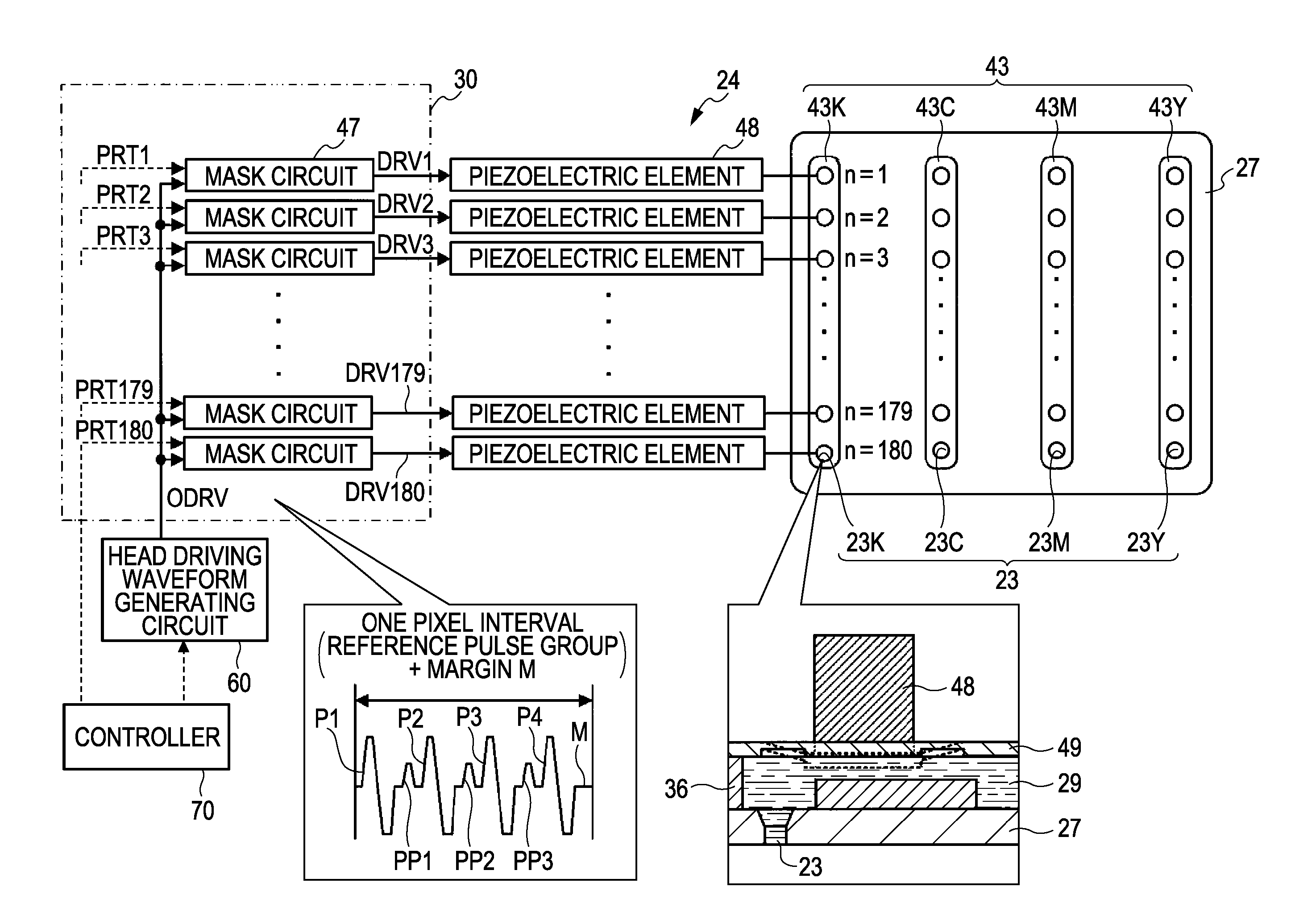
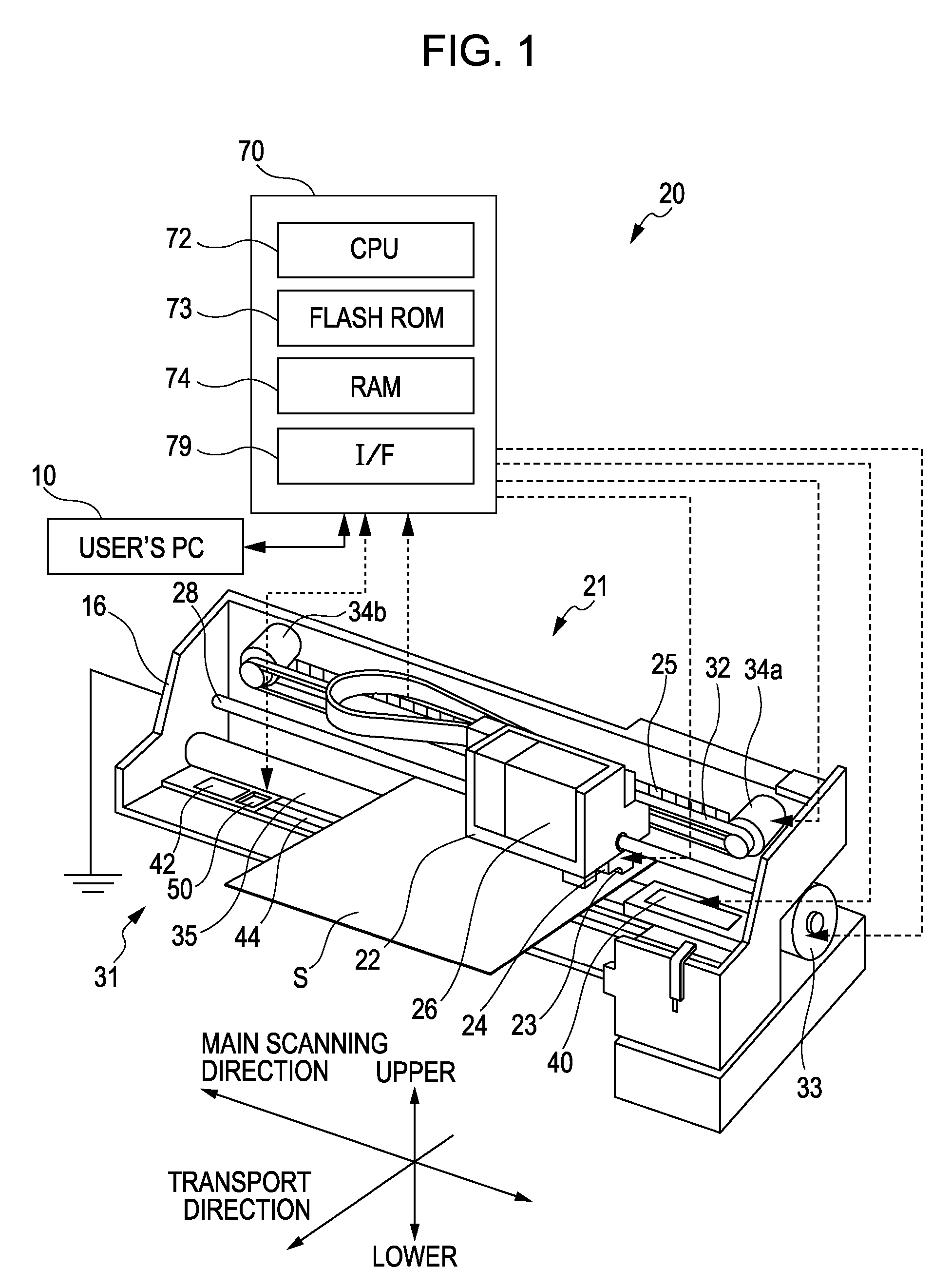
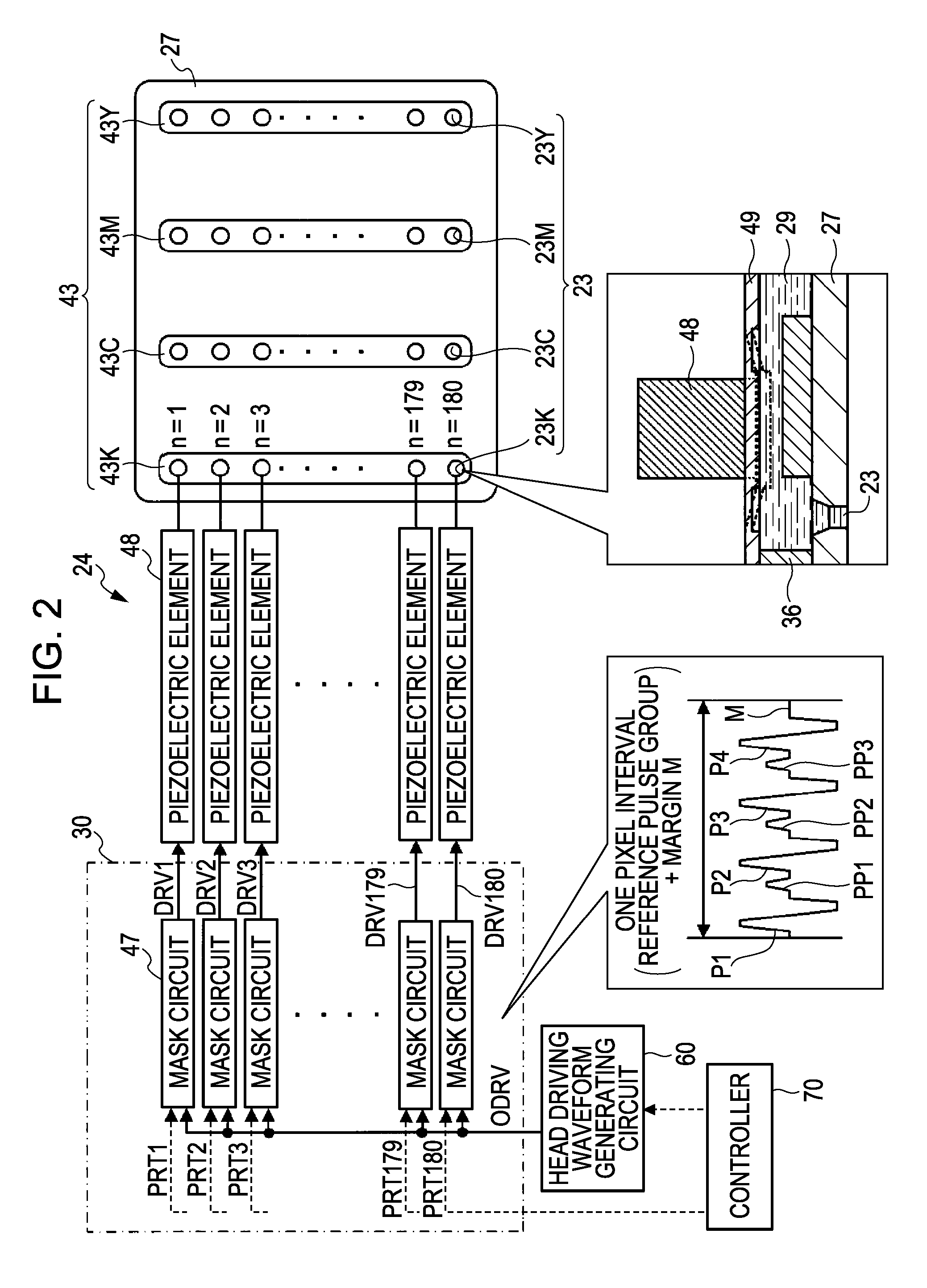
[0025]An embodiment according to the invention will now be described. FIG. 1 is a configuration diagram that shows the schematic configuration of an ink jet printer 20. FIG. 2 is a view that illustrates the electrical connection of a print head 24. FIG. 3 is a view that illustrates a reference pulse group GP1a included in an original signal ODRVa that is used when a normal print job is performed. FIG. 4 is a view that illustrates a reference pulse group GP1b included in an original signal ODRVb when a nozzle 23 is tested. FIG. 5 is a configuration diagram that schematically shows the configuration of a nozzle test device 50.

[0026]As shown in FIG. 1, the ink jet printer 20 of the present embodiment includes a paper feeding mechanism 31, a printer mechanism 21, a capping device 40, a flushing area 42, a nozzle test device 50 and a controller 70. The paper feeding mechanism 31 transports a recording sheet S from the rear side to the front side (transport direction) in the drawing by a ...


PUM


Abstract

A liquid discharging apparatus includes a discharging device, a liquid receiving device, a voltage applying device, and a control device. The discharging discharges liquid from a nozzle to a target on the basis of discharge data, where it is received by a liquid receiving device. The voltage applying device applies a predetermined voltage between the discharging device and the liquid receiving device. When discharging on the basis of the discharge data, the control device controls the discharging device to discharge using a generated discharge data driving signal. When performing nozzle testing, the control device controls the voltage applying device to apply the predetermined voltage between the discharging device and the liquid receiving device and controls the discharging device using a generated test driving signal to discharge liquid from the nozzle to determine on the basis of a detected electrical change whether liquid is discharged from the nozzle.

Description

BACKGROUND[0001]1. Technical Field[0002]The invention relates to a liquid discharging apparatus and a method of controlling the same.[0003]2. Related Art[0004]In an existing art, an ink jet printer is proposed as a liquid discharging apparatus, in which a voltage change that occurs when electrically charged ink droplets are discharged from nozzles of the print head to an ink receiving area is detected by a voltage detection circuit to perform head testing as to whether ink is normally discharged from the nozzles, which is, for example, described in JP-A-2007-118571. The ink jet printer described in JP-A-2007-118571 discharges a plurality of ink droplets from a nozzle to thereby obtain a sufficiently large output waveform at the time of head testing.[0005]The ink jet printer described in JP-A-2007-118571 is able to obtain a sufficiently large output waveform at the time of head testing, for example, by discharging a plurality of ink droplets; however, this may not be effectively obta...

Claims


Application Information

Patent Timeline
Patent Type & Authority Patents(United States)
IPC IPC(8): B41J29/393
CPCB41J2/0451B41J2/04555B41J2/0458B41J2/04581B41J2/04588B41J2/04595B41J2/04596B41J2/125B41J2/2142
Inventor KOMATSU, SHINYASAYAMA, TOMOHIRO
Owner SEIKO EPSON CORP
Why Eureka
Try Eureka