Ground anchor assembly

a technology for ground anchors and assemblies, applied in couplings, traffic signals, roads, etc., can solve the problems of requiring the foundation to be replaced, the installation process is extremely difficult for installation crews, and the flanged base will have difficulty in slipping

Active Publication Date: 2011-10-18
DENT CLIFFORD
View PDF16 Cites 30 Cited by
  • Summary
  • Abstract
  • Description
  • Claims
  • Application Information

AI Technical Summary

Benefits of technology

[0009]The present disclosure is directed to a ground anchor assembly used in conjunction with a support post. In accordance with one embodiment, an assembly is provided that includes at least two threaded studs, an anchor plate having at least two openings sized and shaped to receive the at least two threaded studs, a first fastener for each of the at least two threaded studs attached to a respective stud and bearing against a first side of the anchor plate, and a break-away fastener for each of the at least two threaded studs and attached to the respective stud on an opposite side of the anchor plate and cooperating with the first fastener to retain the stud in position relative to the anchor plate and the other studs.

Problems solved by technology

A difficulty in embedding the anchor bolts during formation of the concrete foundation is maintaining the proper orientation and alignment of the anchor bolts as concrete is poured around them and into the foundation hole or foundation form.
When concrete sets, the flanged base will have difficulty slipping over the misaligned anchor bolts and may be out of plum.
This can make the installation process extremely difficult for installation crews and in some cases require the foundation to be replaced.
While the foregoing design may be satisfactory in some conditions, it requires extra labor to remove the support device.
Moreover, this device can only be used where forms of a certain size and shape allow the support device to be placed thereon.
For these and other reasons, the proposed J-bolt form is unsuitable.

Method used


Image

  • Ground anchor assembly
  • Ground anchor assembly
  • Ground anchor assembly

Examples


Embodiment Construction

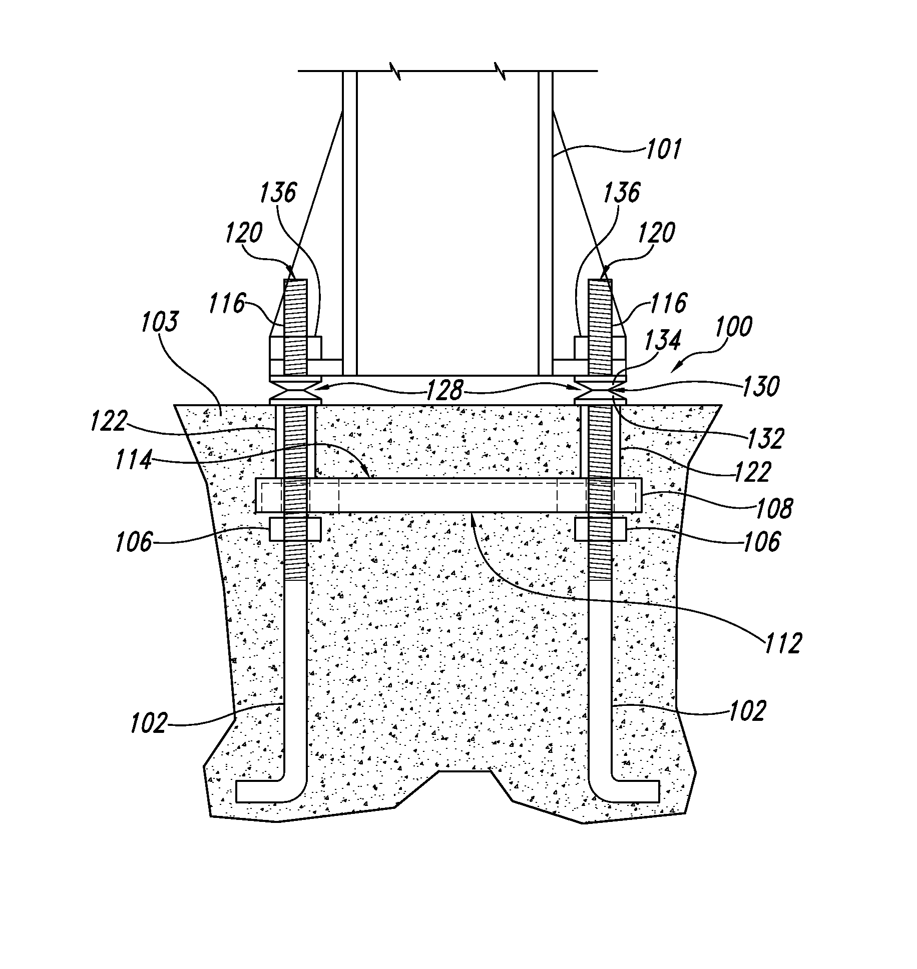
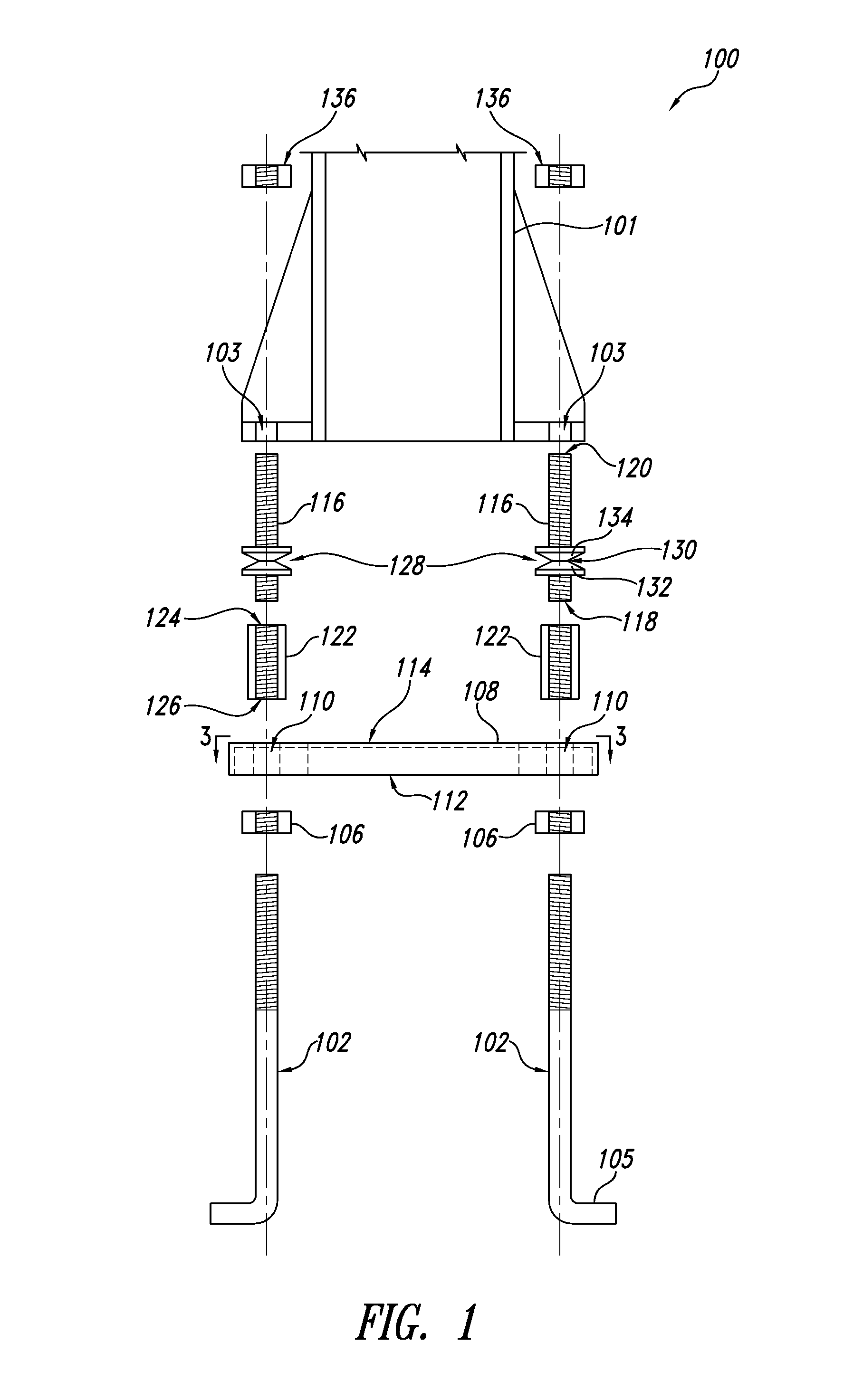
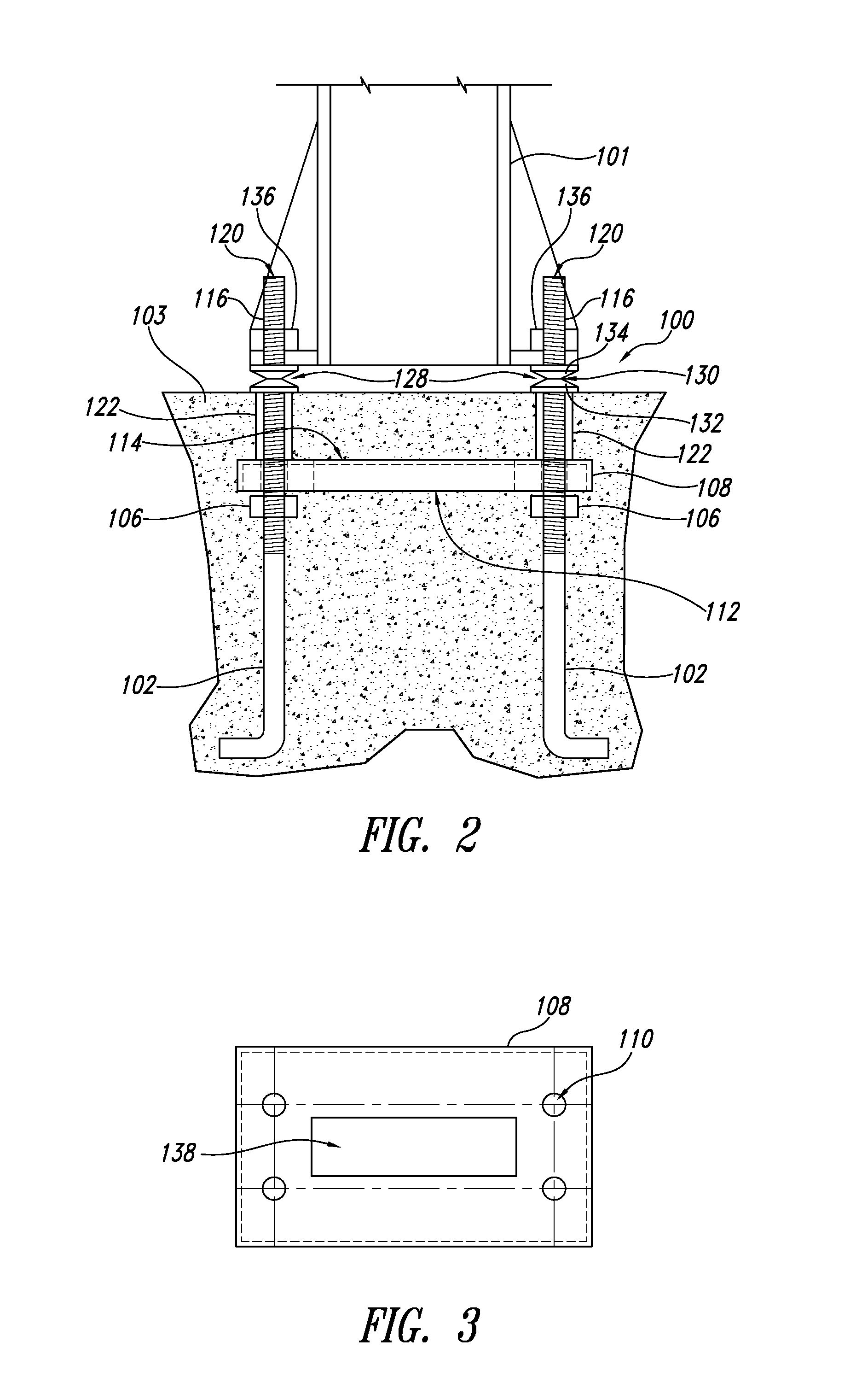
[0022]FIG. 1 illustrates an anchor assembly 100 according to one embodiment to be used for anchoring objects to the ground or other supporting surface or structure. The anchor assembly 100 can be used in applications such as anchoring an article 101 for display or other suitable purpose. The article 101 can include highway signs, luminaries, fences, and guardrails, or any other article desired to be supported. The ground anchor assembly 100 includes at least two threaded studs 102 that in application are secured in a foundation 104 (FIG. 2), such as a concrete or soil foundation.

[0023]The threaded studs 102 can be made of any suitable material that can withstand typical loads imposed thereon by the foundation 104, for example during pouring or hardening of concrete around embedded portions of the anchor assembly 100 in applications where the foundation 104 includes a concrete foundation. The threaded studs 102 can for example be fabricated from a variety of metals, such as steel, al...


PUM


Abstract

A ground anchor assembly includes at least two threaded studs, an anchor plate having at least two openings sized and shaped to receive the at least two threaded studs. The assembly further includes a first fastener for each of the at least two threaded studs attached to the respective stud and bearing against a first side of the anchor plate, and a break-away fastener for each of the at least two threaded studs and attached to the respective stud on an opposite side of the anchor plate. Each break-away fastener cooperates with the corresponding first fastener to retain the corresponding stud in position relative to the anchor plate and the other of the at least two studs.

Description

BACKGROUND[0001]1. Technical Field[0002]The present disclosure is directed to ground anchor assemblies and, in one embodiment, to an embedded assembly of anchor bolts and anchor plate for attaching signposts, luminaries, and the like to a concrete foundation.[0003]2. Description of the Related Art[0004]Highway signs, luminaries, fences, and guardrails are typically supported on posts that are attached to concrete foundations. The support posts typically have a base that is attached to bolts that are embedded in and extend from the concrete foundation. While the base may be separate from or integrally formed with the post, it is important that the base be plum with the concrete foundation so that the post is supported in a substantially vertical orientation.[0005]Anchor bolts extending from the concrete foundation can be in the shape of a J-shaped bolt in which the curved portion is embedded in the concrete and the exposed straight portion is threaded to receive a fastener, such as a...

Claims


Application Information

Patent Timeline
Patent Type & Authority Patents(United States)
IPC IPC(8): E02D27/00
CPCE02D27/32E04B1/4157E04H12/2261Y10T403/1616Y10T403/1683Y10T403/11F16B2200/63
Inventor DENT, CLIFFORD
Owner DENT CLIFFORD
Why Eureka
Try Eureka