Method for operating a hybrid vehicle

a hybrid vehicle and hybrid technology, applied in the direction of engine-driven generators, machines/engines, process and machine control, etc., can solve the problems of temperature spikes in the catalytic converter of the vehicle, delay in torque generation and torque reduction, and inability to allow for a highly dynamic adjustment, etc., to achieve the effect of prolonging the service li

Inactive Publication Date: 2011-10-18
ROBERT BOSCH GMBH
View PDF20 Cites 9 Cited by
  • Summary
  • Abstract
  • Description
  • Claims
  • Application Information

AI Technical Summary

Benefits of technology

[0017]In a motor vehicle drive having at least two drive machines, a method according to an example embodiment of the present invention allows for a precise formation of the combined actual torque, in particular in the zero crossing, even in the case of a strongly varying dynamics in the torque control on one of the drive machines, in particular of a combustion engine, so as to raise the driving comfort. In addition, by suitable use of the other drive machine, in particular an electric machine, high torque dynamics are achieved in the drive, ignition angle interventions being minimized, which in addition to efficiency factor losses at high load may result in temperature spikes in the catalytic converter of the vehicle and may shorten its service life.
[0018]According to the example embodiment of the present invention, the unfiltered combined setpoint torque is used as a basis for the distribution to the power units (operating strategy block). The distribution provides the lead setpoint torque for the slow path of the combustion engine. Thus, the lead setpoint torque is not additionally delayed by the reference-forming element, which allows for a high dynamics of the drive. The lead setpoint torque for influencing the slow influencing path of the first drive machine is obtained from the unfiltered combined setpoint torque before the combined setpoint torque is processed in the reference-forming element. The slow influencing path is the air path in the case of a combustion engine, while the fast influencing path causes an ignition angle adjustment. As the second drive machines the electric machine has a fast influencing path since fundamentally it has a high dynamics.

Problems solved by technology

This causes a delay in torque generation and torque reduction.
The finite adjusting speed of the throttle valve actuator and dynamic filling effects in the intake manifold do not allow for a highly dynamic adjustment of a specified air mass flow and of the combustion engine torque produced thereby.
In addition, by suitable use of the other drive machine, in particular an electric machine, high torque dynamics are achieved in the drive, ignition angle interventions being minimized, which in addition to efficiency factor losses at high load may result in temperature spikes in the catalytic converter of the vehicle and may shorten its service life.

Method used


Image

  • Method for operating a hybrid vehicle
  • Method for operating a hybrid vehicle
  • Method for operating a hybrid vehicle

Examples


Embodiment Construction

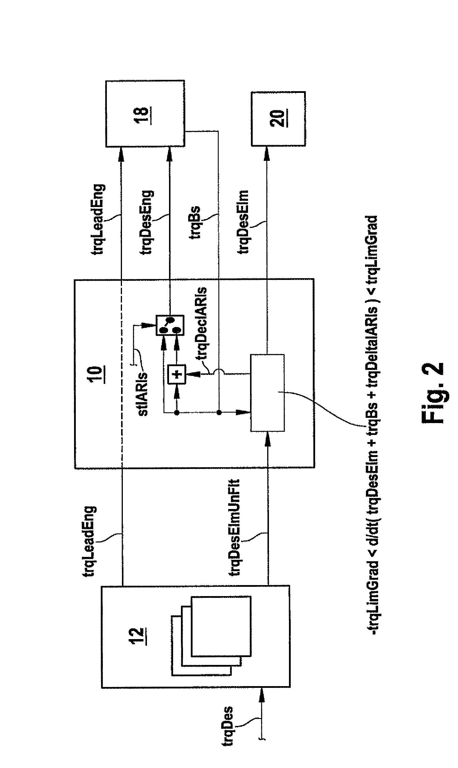
[0035]An exemplary embodiment of the present invention is shown in FIGS. 2 through 5.

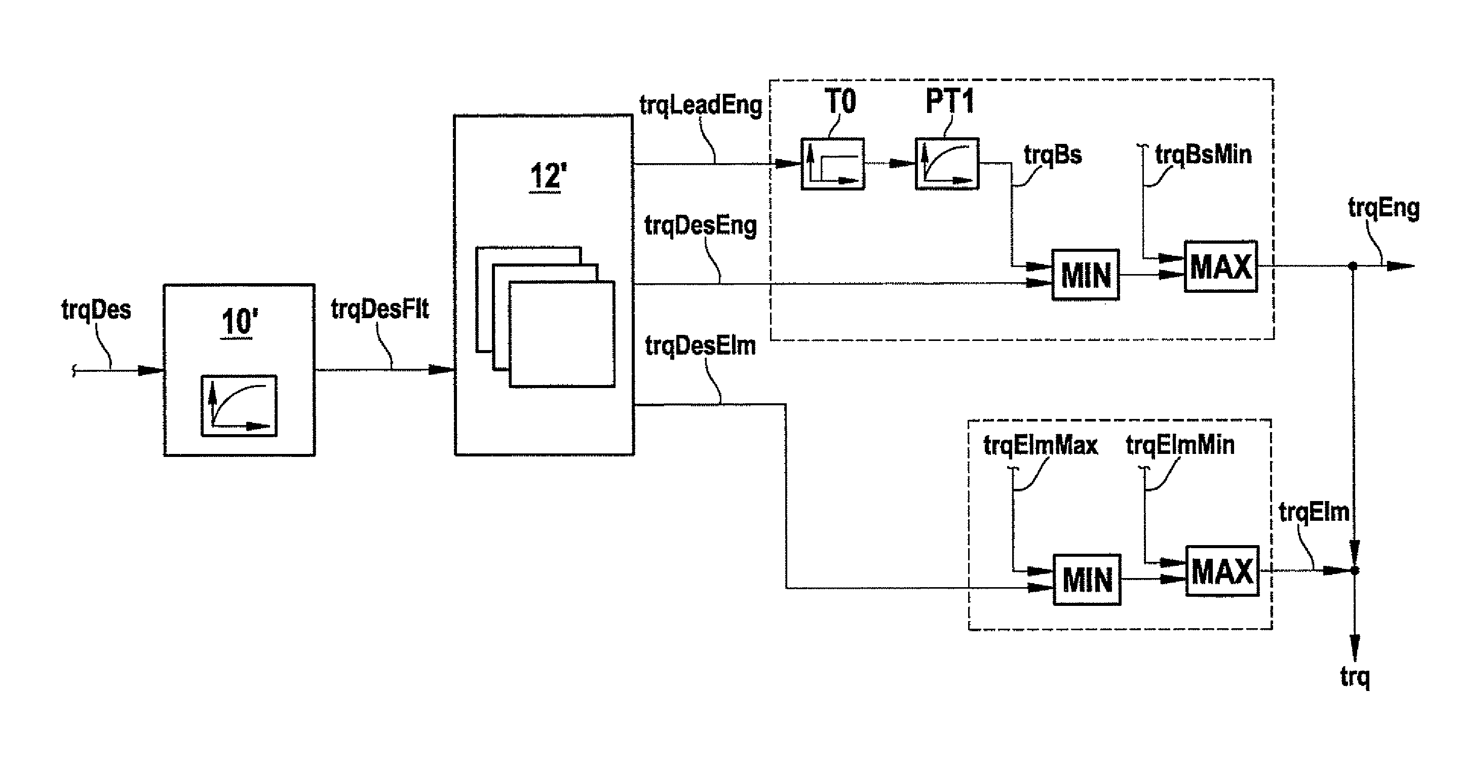
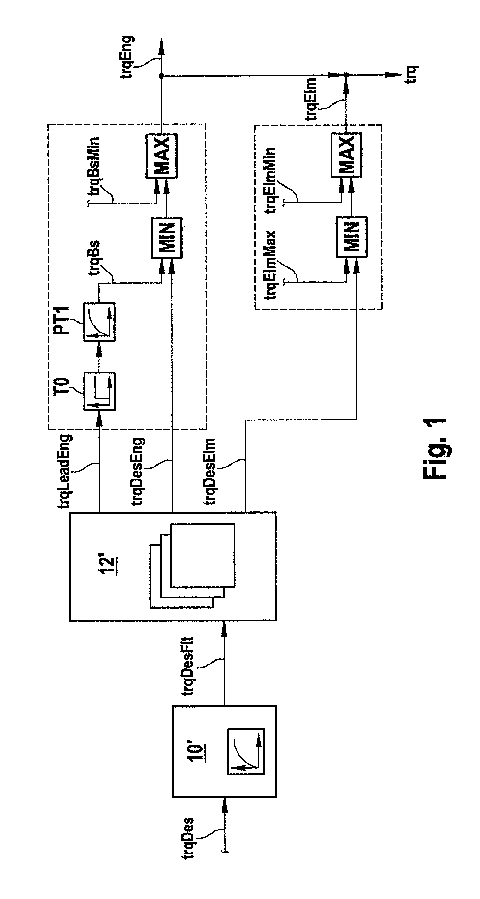
[0036]A combustion engine 18, e.g., an Otto engine, is equipped, by way of example, with a manifold injection system, an electronic accelerator pedal (e-gas, electronic throttle valve) and a catalytic converter. The flywheel of the combustion engine is coupled with an electric machine 20 (crankshaft starter generator), and the actual torques trqEng of combustion engine 18 and trqElm of electric machine 20 add up to form actual torque trq of the drive as a whole, i.e. to form the combined torque of combustion engine 18 and electric machine 20.

[0037]An operating strategy block 12 distributes the combined setpoint torque trqDes requested by the driver or by comfort functions to the lead setpoint torque trqLeadEng for combustion engine 18 and to the unfiltered setpoint torque trgDesElmUnFlt of electric machine 20 in light of energetic and emission considerations (FIG. 2).

[0038]For reasons of clarity, no...


PUM


Abstract

A method for operating a hybrid drive having at least one first and one second drive-connected drive machine, in which an actual torque of at least one of the drive machines is influenced by a reference-forming element in that, from a combined setpoint torque, a first setpoint torque is formed for a slow influencing path and a second setpoint torque is formed for a fast influencing path for the first drive machine and a setpoint torque is generated for a fast influencing path of the second drive machine. A provision is made for the lead setpoint torque for influencing the slow influencing path of the first drive machine to be obtained from the unfiltered combined setpoint torque before the combined setpoint torque is processed in the reference-forming element.

Description

FIELD OF THE INVENTION[0001]The present invention is based on a method for operating a hybrid vehicle.BACKGROUND INFORMATION[0002]Recently, the reduction of emissions and fuel consumption resulted in the further development of hybrid drives for motor vehicles. The aim is to operate the combustion engine in the range of favorable efficiency factors, to switch it off when the vehicle is at a standstill or at low vehicle speeds, and to drive electrically and to utilize braking energy by recuperation. For example, in parallel hybrids the torques of the combustion engine and of one or multiple electric machines are added. The electric machines are connected, e.g., as starter generators to the belt drive or to the crankshaft of the combustion engine.[0003]Rapid load changes or switching operations may induce a bucking movement in the vehicle, in which typically the engine's rotating mass together with the transmission's rotating mass swings against the reduced vehicle mass. In addition, o...

Claims


Application Information

Patent Timeline
Patent Type & Authority Patents(United States)
IPC IPC(8): B60W10/06
CPCB60W10/06B60W10/08B60W20/102B60L2240/423B60L2240/441B60W2510/0619B60W2510/0638B60W2510/0671B60W2710/0666B60W2710/083Y02T10/6286Y02T10/642F16H2059/144B60W20/11B60L15/2045Y02T10/72B60L50/62B60L50/16Y02T10/62Y02T10/64Y02T10/7072Y02T10/70B60W2050/0052
Inventor HUBER, THOMASFALKENSTEIN, JENS-WERNER
Owner ROBERT BOSCH GMBH
Why Eureka
Try Eureka