Lightweight combat helmet

a lightweight, helmet technology, applied in the field of combat helmets, can solve the problems of increasing the weight and cost of protective helmets without providing comfort to wearers

Inactive Publication Date: 2011-11-01
USA REPRESENTED BY THE SEC OF THE NAVY
View PDF59 Cites 52 Cited by
  • Summary
  • Abstract
  • Description
  • Claims
  • Application Information

AI Technical Summary

Benefits of technology

[0006]Accordingly, it is an object of the present invention to provide a combat helmet that offers the wearer protection from an incoming projectile.
[0007]Another object of the present invention is to provide a lightweight combat helmet.

Problems solved by technology

These methods increase the weight and cost of the protective helmets without providing a comfort fit to the wearer.

Method used


Image

  • Lightweight combat helmet
  • Lightweight combat helmet
  • Lightweight combat helmet

Examples


Embodiment Construction

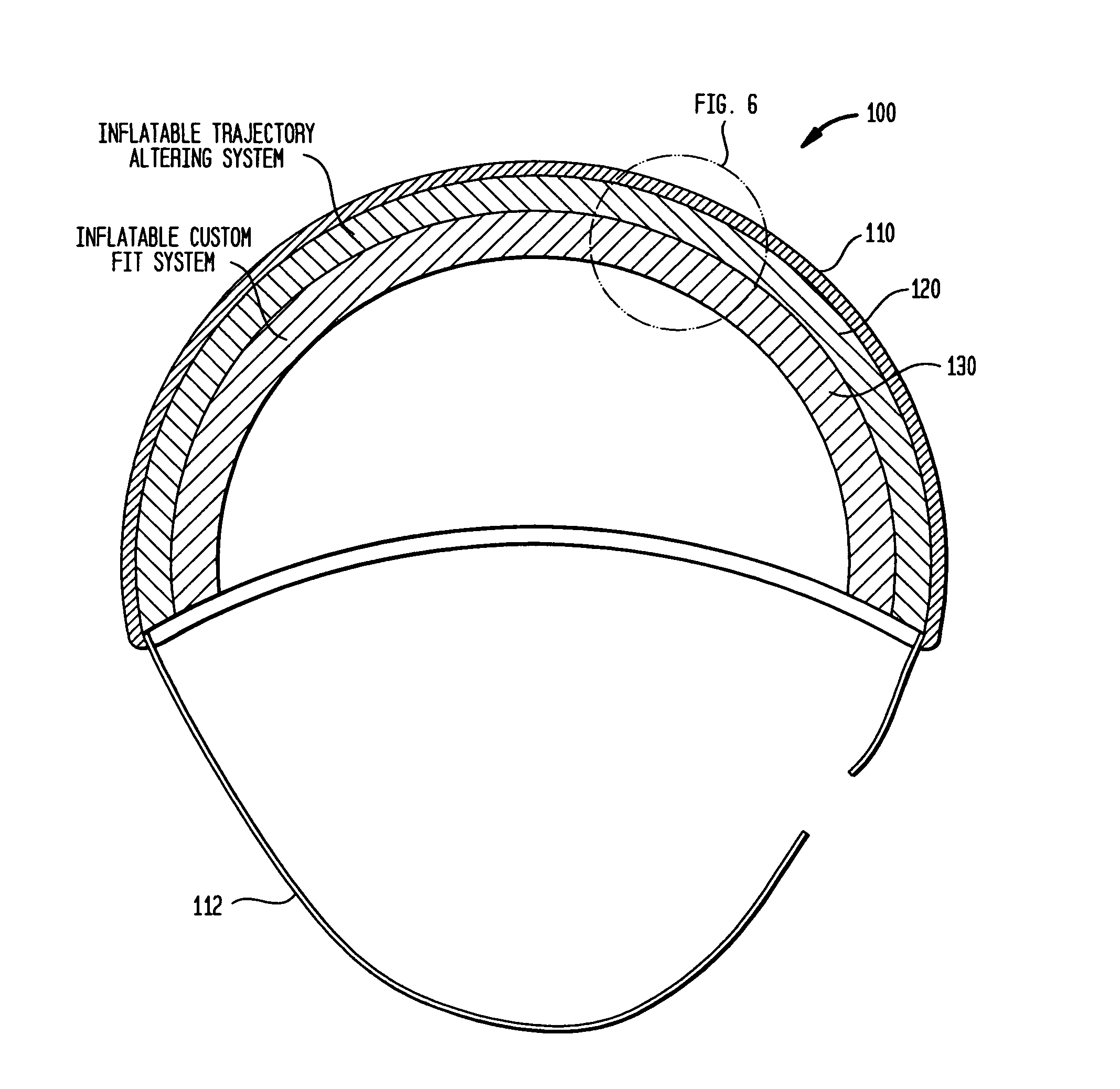
[0019]Prior to describing the combat helmet of the present invention, an inflatable trajectory altering system that forms a core element for the combat helmet will first be described. Details of this core element can be found in each of U.S. Pat. Nos. 6,997,218 and 7,213,497, the contents of which are hereby incorporated by reference. However, in order to provide a complete description and understanding of the present invention, various embodiments of the core element will be described briefly herein.

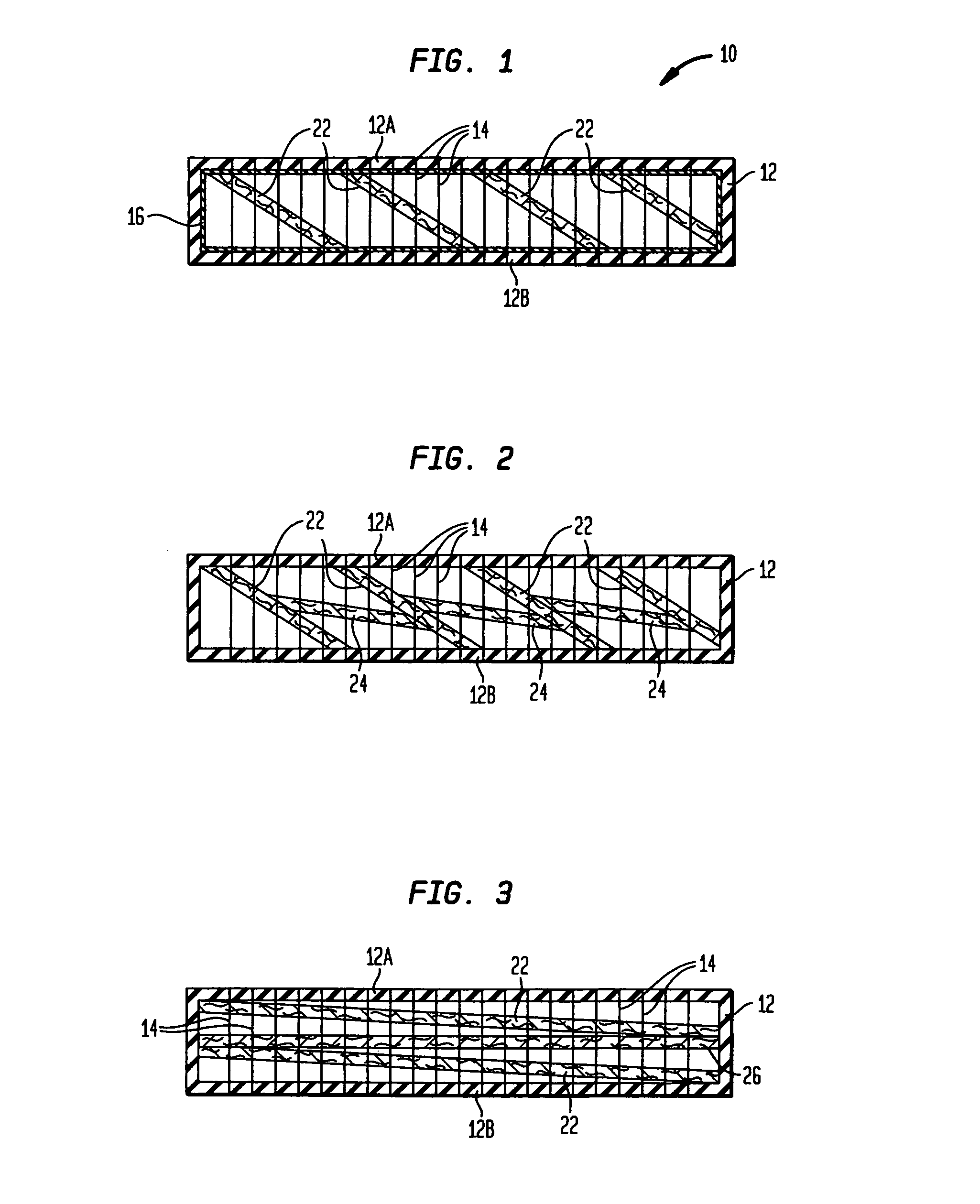
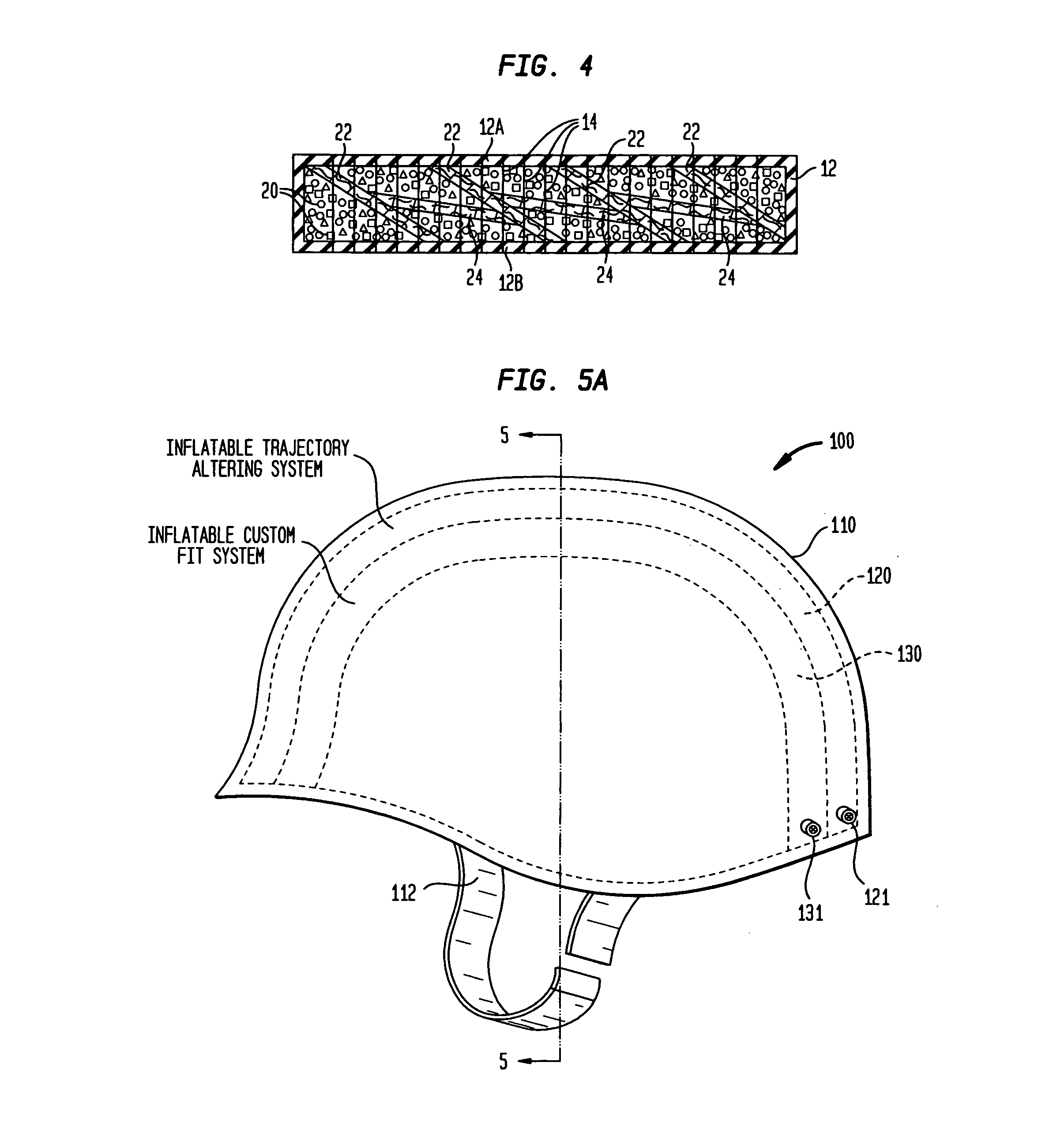
[0020]Referring now to the drawings, and more particularly to FIG. 1, one embodiment of an inflatable trajectory altering system used by the present invention is shown in its inflated state and is referenced generally by numeral 10. System 10 has an outer wall structure 12 made from a flexible and fluid-impermeable material that defines a plenum. More specifically, wall structure 12 has major opposing walls 12A and 12B that are spaced apart from one another when the interior volume defi...


PUM


Abstract

A lightweight combat helmet has a rigid helmet shell with first and second flexible and fluid impermeable receptacles nested within the helmet shell. The first receptacle is filled with structures and substances that alter a trajectory of an incoming projectile. When filled, the second receptacle conforms to a wearer's head.

Description

ORIGIN OF THE INVENTION[0001]The invention described herein was made in the performance of official duties by employees of the Department of the Navy and may be manufactured, used, licensed by or for the Government without payment of any royalties thereon.CROSS-REFERENCE TO RELATED PATENT APPLICATIONS[0002]This patent application is co-pending with one related patent application entitled “LIGHTWEIGHT COMBAT HELMET” (Navy Case No. 98800) by the same inventors as this patent application.FIELD OF THE INVENTION[0003]The invention relates generally to combat helmets, and more particularly to a lightweight combat helmet that alters a projectile's trajectory as the projectile passes through a filled receptacle thereof.BACKGROUND OF THE INVENTION[0004]State-of-the-art combat helmets used by the military and police riot / SWAT forces are constructed from layers of fabric (e.g., commercially-available aramid fabrics such as SPECTRA, KEVLAR, etc., or polypropylene, polyethylene or high-performan...

Claims


Application Information

Patent Timeline
Patent Type & Authority Patents(United States)
IPC IPC(8): F41H1/04A42B3/06A42B3/12A42B3/00
CPCA42B3/061A42B3/122F41H1/04F41H5/023
Inventor GARCIA, FELIPEWOODALL, ROBERTDOYLE, CHRISREITMEYER, GREG
Owner USA REPRESENTED BY THE SEC OF THE NAVY
Why Eureka
Try Eureka