Electrolyser and components therefor

a technology of electrolyser and components, applied in the direction of electrolysis components, instruments, optics, etc., can solve the problems of increased space requirement of electrolyser modules, inconvenient and time-consuming maintenance of electrolyser modules, and insufficient removal conditions of electrolyser modules of this design

Active Publication Date: 2011-11-15
HYDROGENICS CORP
View PDF70 Cites 167 Cited by
  • Summary
  • Abstract
  • Description
  • Claims
  • Application Information

AI Technical Summary

Problems solved by technology

The extra equipment required in these scenarios has the drawback that it is costly and it increases the space requirement for the electrolyser module.
In addition, the extra pieces required to connect the degassing chambers to the cells provide opportunities for leakage, resulting in costly and time-consuming maintenance of the electrolyser module.
It has now been determined that integrated electrolyser modules of this design do not provide optimal conditions for removal of entrained gas from the liquid.
In addition, such designs do not provide optimal conditions for increasing overall current efficiency of the electrolysis reactions and do not allow for effective differential pressure control between the anodic and cathodic electrolysis chambers.

Method used


Image

  • Electrolyser and components therefor
  • Electrolyser and components therefor
  • Electrolyser and components therefor

Examples


Embodiment Construction

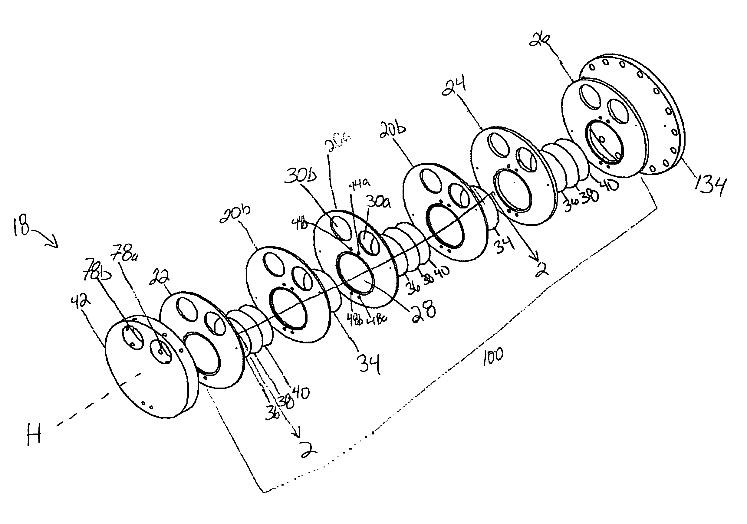
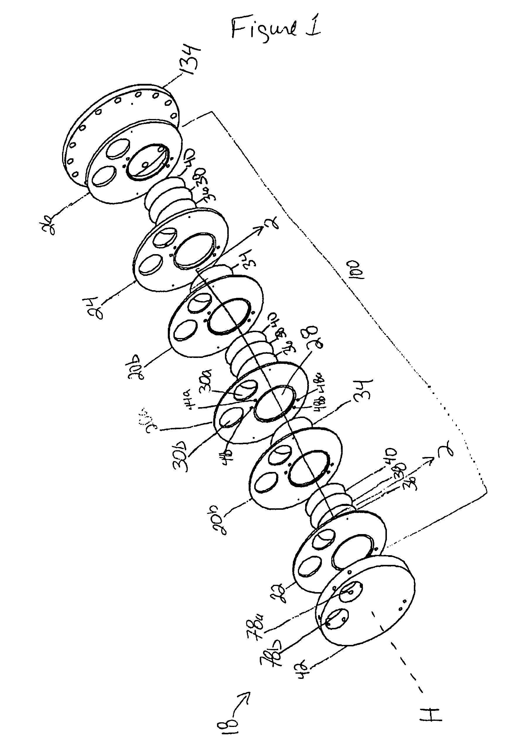
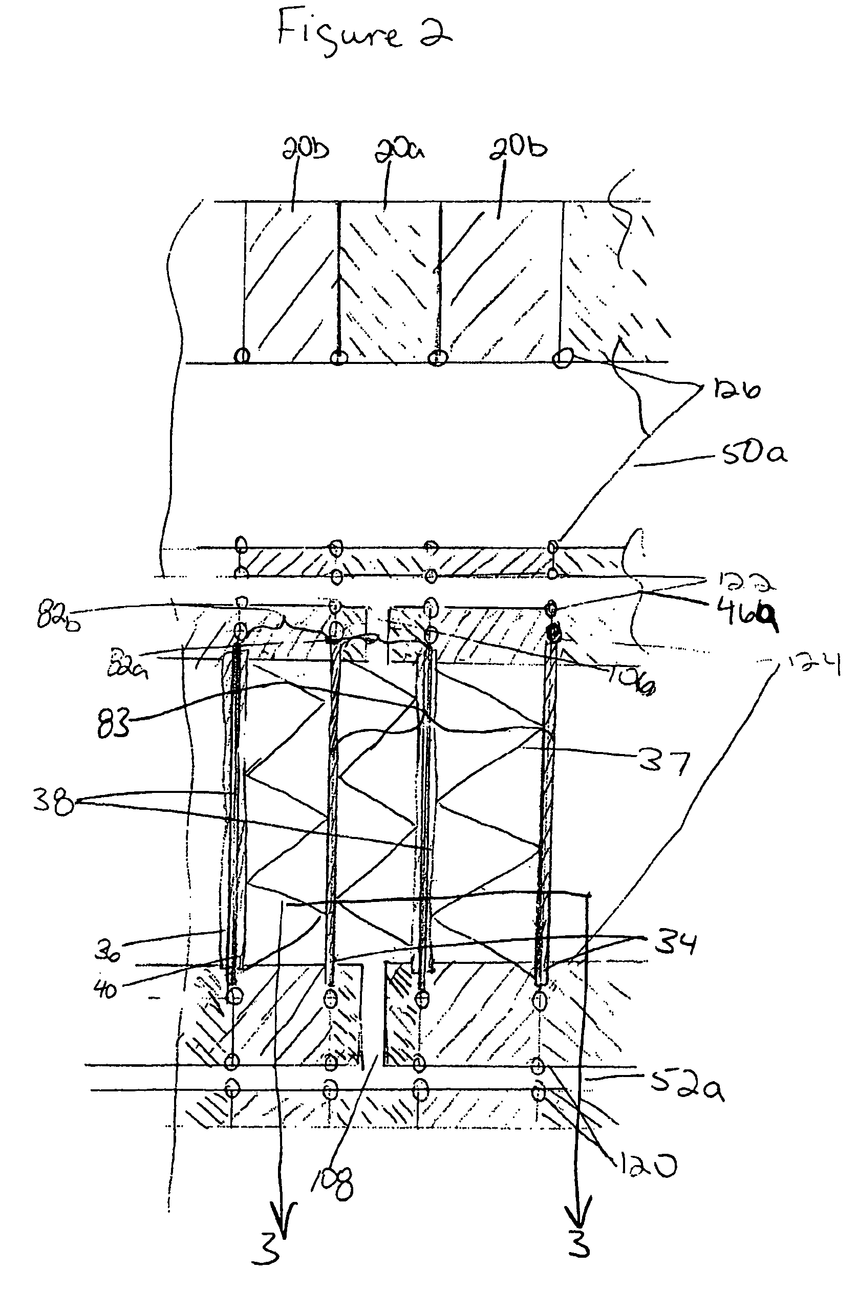
[0046]An electrolyser module in accordance with an aspect of the present invention is shown generally at 18 in FIGS. 1-11 (for ease of reference, FIG. 1 shows a portion of an electrolyser module; FIG. 11 shows a schematic sectional view of the entire electrolyser module). Electrolyser module 18 includes cell plates 20, end plate 22, transfer plates 24 and 26, and return plate 42. Electrolyser module 18 further includes bipolar plates 34, anode plates 36, cathode plates 40, and gas impermeable membranes 38 all as described below. Electrolyser module 18 thus comprises a plurality of electrolysis cells 83 having anodic and cathodic electrolysis chambers 82a and 82b arranged together. Each cell plate 20 defines one or more electrolysis chamber openings 28 and one or more degassing chamber openings 30 as described further below. Electrolysis chamber opening 28a functions as an anode electrolysis chamber 82a when associated with an anode when the electrolyser module is assembled. Cell pla...


PUM

PropertyMeasurementUnit
thicknessaaaaaaaaaa
thicknessaaaaaaaaaa
pressureaaaaaaaaaa

Abstract

The present invention is directed to cell plates for an electrolyser module and to an electrolyser module incorporating the plates. The plates comprise an electrolysis chamber opening, at least one degassing chamber opening, and at least one gas-liquid conduit opening. The plates further comprise a channel connecting the electrolysis chamber opening and the gas-liquid conduit opening. The present invention is directed further to a process and apparatus for separating a gas-liquid mixture generated at an electrolysis cell.

Description

FIELD OF THE INVENTION[0001]The present invention relates to the design of electrochemical cells and electrochemical systems, and more particularly to an electrolyser and components therefor.BACKGROUND OF THE INVENTION[0002]Electrosynthesis is a method for production of chemical reaction(s) that is electrically driven by passage of an electric current, typically direct current (DC), through, for example, a liquid, such as an electrolyte, between an anodic electrode (anode) and a cathodic electrode (cathode). An electrochemical cell is used for electrochemical reactions and comprises an anode and cathode which are in intimate contact with the electrolyte. The current is generated from an external power source and is passed between the two electrodes. Each electrode typically comprises about half of the electrochemical cell. The rate of production is proportional to the current flow in the absence of parasitic reactions. For example, in a liquid alkaline water electrolysis cell, DC is...

Claims


Application Information

Patent Timeline
Patent Type & Authority Patents(United States)
IPC IPC(8): C25B9/20C25B1/08C25B9/17
CPCC25B9/18C25B9/20C25B15/08Y02E60/366C25B9/70C25B9/73Y02E60/36
Inventor HINATSU, JAMES T.STEMP, MICHAEL C.
Owner HYDROGENICS CORP
Why Eureka
Try Eureka