Organic electrolyte capacitor
a capacitor and electrolyte technology, applied in the field of organic electrolyte capacitors, can solve the problems of deterioration of the negative electrode, deterioration of the electrode, and decrease in capacity, and achieve the effects of improving the conductivity of the electrode, low internal resistance, and high performan
- Summary
- Abstract
- Description
- Claims
- Application Information
AI Technical Summary
Benefits of technology
Problems solved by technology
Method used
Image
Examples
first embodiment
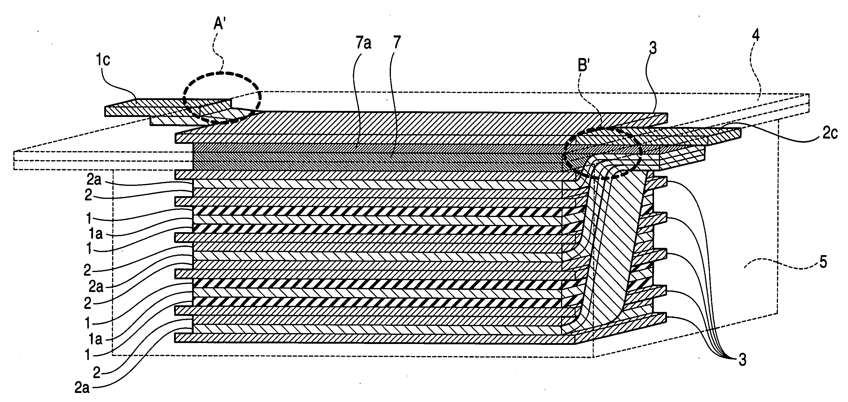
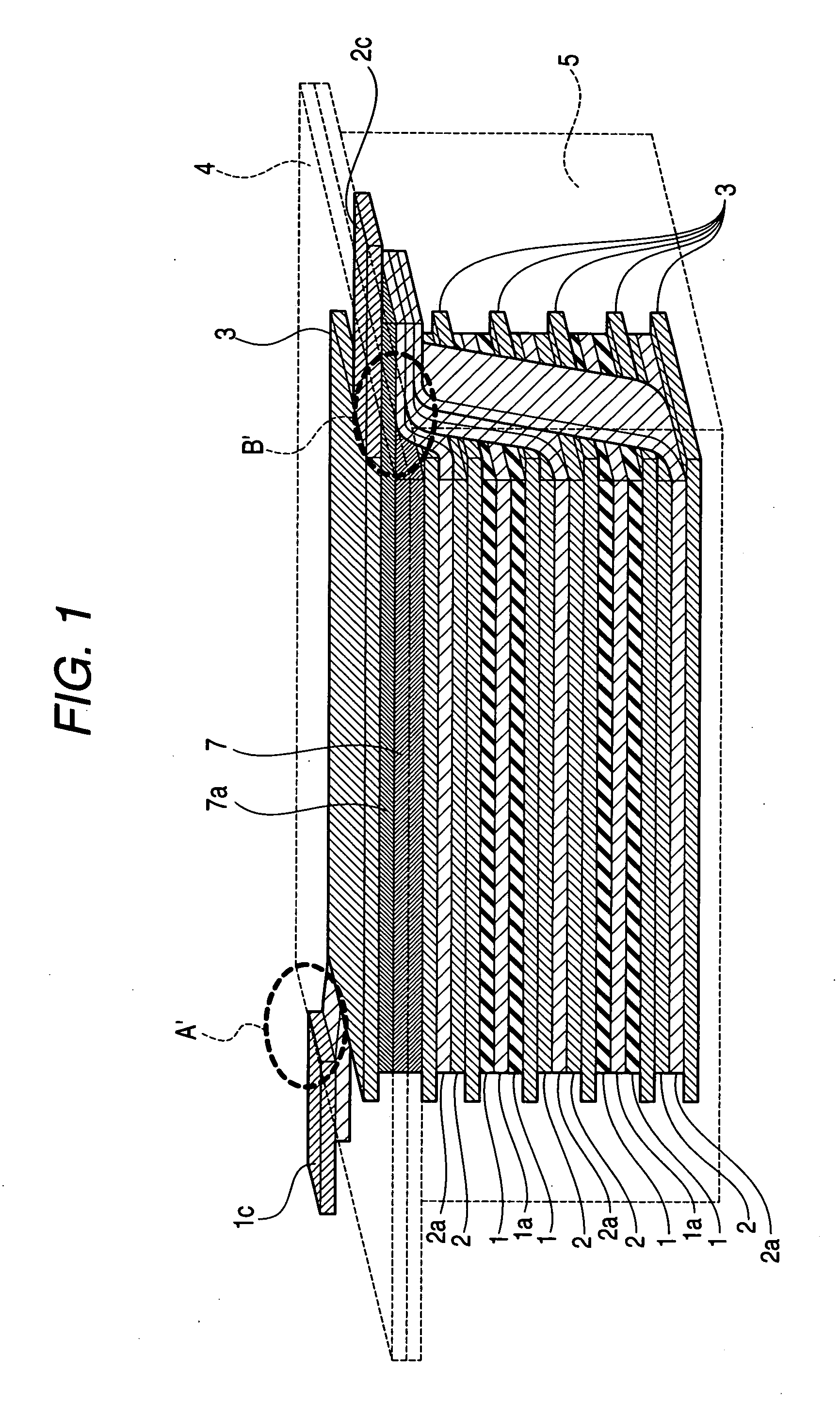
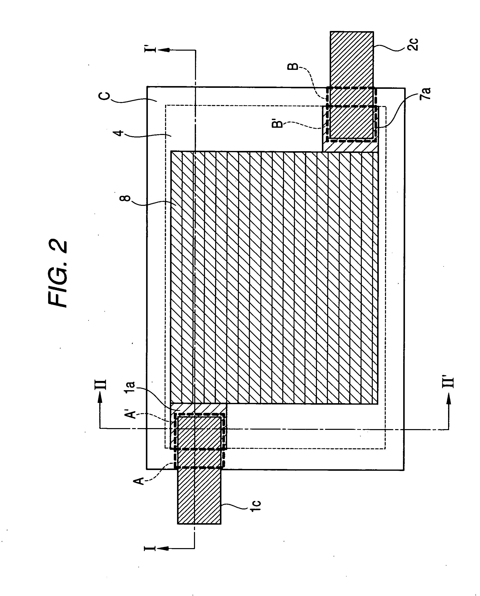
[0201]FIG. 1 is a perspective view of a film-type capacitor according to the first embodiment of the organic electrolyte capacitor of the invention. FIG. 2 is a plan view of the first embodiment, FIG. 3 is a cross-sectional view taken along the ling I-I′ shown in FIG. 2, and FIG. 4 is a cross-sectional view taken along the line II-II′ shown in FIG. 2.
[0202] In the first embodiment, a three-electrode-laminated unit 8 is formed by providing a lithium electrode 7 on an electrode-laminated unit 6, in which electrode pairs including positive and negative electrodes are laminated sequentially.
[0203] In the first embodiment, the electrode-laminated unit 6 is formed using three negative electrode current collectors 2a and two positive electrode current collectors 1a. The positive and negative electrode current collectors 1a and 2a have holes penetrating the front and rear surfaces, and at least part of the through-holes are blocked with conductive materials 1b and 2b that are different fr...
second embodiment
[0214] Hereinafter, the second embodiment will be described. FIG. 13 is a plan view showing the second embodiment. FIG. 14 is a cross-sectional view taken along the line I-I′ shown in FIG. 13. Since the same numerals in the first and second embodiments denote the same components, only different portions will be described in detail.
[0215] As shown in FIG. 14, the sheet-shaped lithium electrodes 7 are disposed in the center of the roll-type structure in the second embodiment. The lithium electrodes 7 are formed on both surfaces of the lithium electrode current collector 7a. The positive electrode 1 is formed on a surface of a ribbon-shaped positive electrode current collector 1a, and the negative electrode 2 is formed on a surface of a ribbon-shaped negative electrode current collector 2a. Separator 3, negative electrode (2+2a), separator 3, and positive electrode (1+1a) are overlapped in this order and wound elliptically with the lithium electrode current collector 7a having the lit...
first example
[0228] (Manufacturing Method of PAS Slurry for the Negative Electrode)
[0229] PAS is synthesized by thermally treating a 0.5 mm-thick phenolic resin plate in a siliconit electric furnace, which increases the temperature up to 500° C. at a speed of 50° C. / hour, and then up to 650° C. at a speed of 10° C. / hour under nitrogen atmosphere. The PAS plate obtained in this way is grinded by a ball mill so as to obtain PAS powder having an average particle size of 7 μm. The H / C ratio of the PAS powder is 0.22.
[0230] Next, 92 parts by weight of the above-mentioned PAS powder, 4 parts by weight of acetylene black powder, 4 parts by weight of SBR, 3.2 parts by weight of carboxymethylcellulose, and 120 parts by weight of ion-exchanged water are mixed sufficiently to obtain a slurry.
[0231] (Measurement of the Capacitance Per Unit Weight of the Negative Electrode)
[0232] The slurry is coated and dried on a surface of an 18 μm-thick copper foil, and then pressed so as to form a PAS negative elect...
PUM
 Abstract
Description
Claims
Application Information
 - R&D
- Intellectual Property
- Life Sciences
- Materials
- Tech Scout
- Unparalleled Data Quality
- Higher Quality Content
- 60% Fewer Hallucinations
Browse by: Latest US Patents, China's latest patents, Technical Efficacy Thesaurus, Application Domain, Technology Topic, Popular Technical Reports.
© 2025 PatSnap. All rights reserved.Legal|Privacy policy|Modern Slavery Act Transparency Statement|Sitemap|About US| Contact US: help@patsnap.com


