
Camera for medical, particularly dental use

a camera and dental technology, applied in the field of cameras for medical, can solve the problems of inability to localize sensitive controls, difficulty in ensuring accuracy, so as to preserve the quality of precision and repetitivity

Inactive Publication Date: 2011-11-22
SOPRO SA
View PDF7 Cites 6 Cited by
  • Summary
  • Abstract
  • Description
  • Claims
  • Application Information

AI Technical Summary

Benefits of technology

"The present invention proposes a camera for medical use, particularly dental, which has a sensor and its support circuit separated from the detection zone to maintain accuracy and repetitiveness. The camera has a casing with a sensor element and an electrostatic foam element positioned between the sensor element and the inner face of the casing. The foam element is in a slightly compressed state and has a higher resistivity than the central part of the foam element to facilitate positioning of the sensor and its support circuit in the casing. The resistivity of the foam element in contact with the inner face of the casing is less than 5 MΩ.cm."

Problems solved by technology

Now, this type of pedal-control is used for numerous instruments, particularly in dental surgeries, with the result that it may be awkward for the practitioner to multiply such controls.
One of the difficulties encountered in the use of such controls on dental cameras for ensuring “freezing” of an image, is a result of the fact that, contrary to the conventional control knobs which allow a tactile localization, the sensitive controls can themselves only be localized by the practitioner visually, which is not acceptable in the present case insofar as his visual concentration must imperatively be directed on the operative field.
Now, it has proved that, for various reasons, due in particular to the space requirement, to the global design of the camera, to the aesthetics of the body thereof, or to the presence of various components on the support circuit, it is not possible, in certain configurations, to dispose the sensor and the electronic circuit associated therewith in contact with the inner face of the body of the camera.
Now, it is known that, when it is desired that the sensor detects a user's finger precisely and repetitively, it cannot be envisaged to separate the electronic circuit from the sensor in order to position the latter against the inner wall of the body in the immediate proximity of the zone of detection.
In effect, it has been observed that the cord link which is in that case established between these two elements has for consequence to destroy the precision and correct repetitivity of the position of detection, insofar as the linking cords become an integral part of the sensor, their position and their length influencing the detection.

Method used


Image

  • Camera for medical, particularly dental use
  • Camera for medical, particularly dental use

Examples


Embodiment Construction

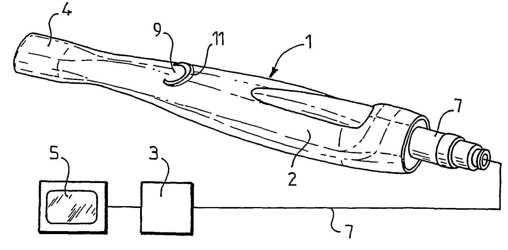
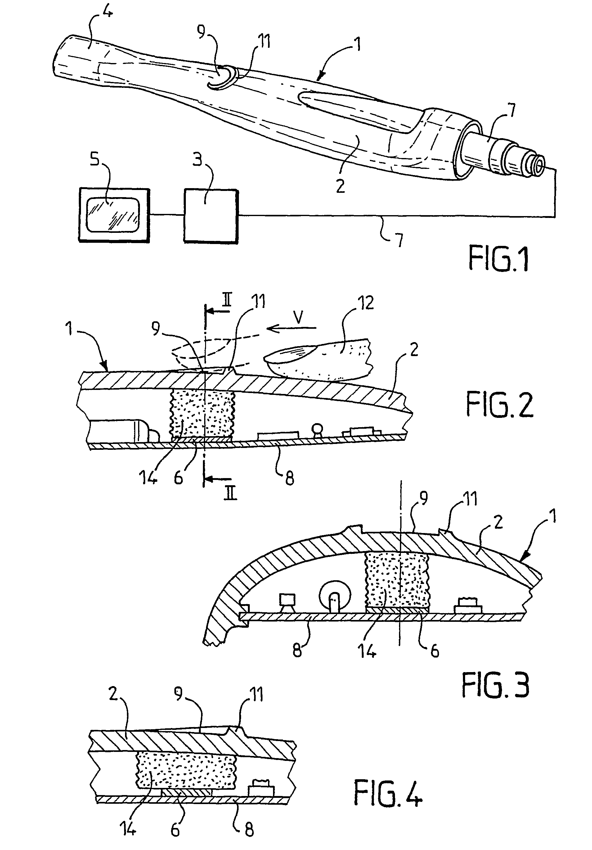
[0019]FIGS. 1 to 3 show a dental camera 1 which is constituted by an elongated body 2, of substantially ellipsoidal cross section, comprising at its anterior end 4 a shot-taking lens and at its other end a cord 7 by which it is linked with electronic means 3 for supply and for managing the images which are displayed on a monitor 5.

[0020]According to the invention, this camera 1 comprises a control device allowing the user to “freeze” an image, i.e. to immobilize it on the monitor 5. This control device comprises a sensitive sensor associated with an electronic circuit, and a zone of surface discontinuity made on the casing 2.

[0021]The zone of surface discontinuity is formed by a boss 11 in the form of a C whose opening is oriented towards the anterior end 4 of the camera and which projects slightly with respect to the upper face of the body 2. The boss 11 is disposed upstream of a zone 9 (called detection zone 9) with respect to the movement of natural displacement of a finger 12 of...


PUM


Abstract

The medical, particularly dental imaging camera including an elongated housing (2) that can be held by a single hand of a user and provided, at its front end, with an imaging element, this housing (2) including a sensitive control element capable of freezing, on a display (5), an image selected by the user, this control element having a detection area (9) situated on the housing (2) that is delimited by a surface discontinuity such as a recess or a relief (11). The housing (2) encloses a sensor element associated with an electronic driving circuit and an electrostatic foam element whose one end is applied against the sensor element and whose opposite end is applied against an area of the inner face of the housing (2) located to the right of the detection area (9).

Description

BACKGROUND OF THE INVENTION[0001]1. Field of the Invention[0002]The present invention relates to a camera for medical, and particularly dental, use.[0003]2. Description of the Related Art[0004]In the medical domain, and more particularly in the dental domain, micro-cameras are known, whose lens is disposed at the end of a hand piece and which comprise on the body thereof a control knob making it possible to trigger off shot-taking or to capture a specific image.[0005]Such micro-cameras, particularly when they are used in applications where it is necessary to “freeze” an image, are controlled by a specific pedal actuated by the user's foot. In effect, it has been observed that, particularly in this type of applications, the simple actuation of a control knob fast with the camera, however gentle its release, led to generating a movement of the camera having for effect to blur the image which it was desired to “freeze”. Now, this type of pedal-control is used for numerous instruments, ...

Claims


Application Information

Patent Timeline
Patent Type & Authority Patents(United States)
IPC IPC(8): H04N7/18A61B1/045A61B1/24
CPCA61B1/00039A61B1/24A61B1/045A61B1/00042A61C19/00
Inventor BOYER, PHILIPPEMAZUIR, ALAIN
Owner SOPRO SA
Learn More