Laparoscopic surgical instrument

a surgical instrument and laparoscopic technology, applied in the field of laparoscopic surgical instruments, can solve the problems of difficult use of incorporating a bent handle design, difficult to perform long procedures, awkward use of instruments for any extended period of time or for long procedures, etc., to facilitate the performance of surgical procedures, improve accuracy in performing, and reduce the effect of precision and for

Inactive Publication Date: 2011-12-20
SHORTI RAMI +1
View PDF79 Cites 952 Cited by
  • Summary
  • Abstract
  • Description
  • Claims
  • Application Information

AI Technical Summary

Benefits of technology

[0008]The present invention also features a laparoscopic surgical instrument specifically configured for use in surgical procedures requiring less precision and force, the laparoscopic surgical instrument comprising: (a) an ergonomic handle comprising a handle grip extending from a riser, the handle grip comprising a tubular body having a longitudinal axis oriented between 60 and 70 degrees from a longitudinal axis of the riser, the handle grip being sized and configured to orient a hand of a surgeon in a functional position; and (b) a working shaft having a proximal end supported by the riser, the working shaft having an elongate configuration and a distal working end configured to receive a surgical tool to be manipulated by the surgeon via the handle to perform a surgical function, the laparoscopic surgical instrument providing limited force generation to the working end through manipulation of the handle for improved accuracy in performing specific surgical procedures.
[0009]The present invention further features a method for facilitating performance of a surgical procedure, the method comprising: (a) providing a laparoscopic surgical instrument configured to be ergonomic and anthropometrically correct, the laparoscopic surgical instrument comprising a tubular handle having a riser and a handle grip; (b) causing the laparoscopic surgical instrument to orient a hand of a surgeon in a functional position upon grasping the handle; (c) facilitating actuation of a trigger of an actuating mechanism supported by the handle by a finger of the hand of the surgeon; (d) causing the actuating mechanism to displace a working shaft in a same direction of displacement of the trigger, the working shaft configured to couple a surgical tool to be manipulated by the surgeon via the handle and the actuating mechanism to perform a surgical function; (e) facilitating the locking of the actuating mechanism in any one of a plurality of positions; and (f) facilitating the release of the locking mechanism by a finger of the hand of the surgeon, the release being located in an anthropometrically correct position.

Problems solved by technology

Because of this, the instruments were awkward and difficult to use for any extended period of time or for lengthy procedures.
Moreover, they were not designed for complex internal surgical operations, such as suturing.
Surgical instruments incorporating a bent-handle design can be difficult to use, and can also cause injury to the surgeon.
These positions are not only awkward, but they also encourage the development of carpal tunnel syndrome and chronic joint stress by positioning or orienting the hand in non-natural or non-functional positions.
This creates undesirable distractions, delays, and other problems during a surgical procedure.
Additionally, the bent-handle design does not efficiently translate force from the handle to the functional end of the instrument.
This undesirable movement may be translated along the instrument to the functional end, thus compromising stability and inducing unwanted movement.

Method used


Image

  • Laparoscopic surgical instrument
  • Laparoscopic surgical instrument
  • Laparoscopic surgical instrument

Examples


Embodiment Construction

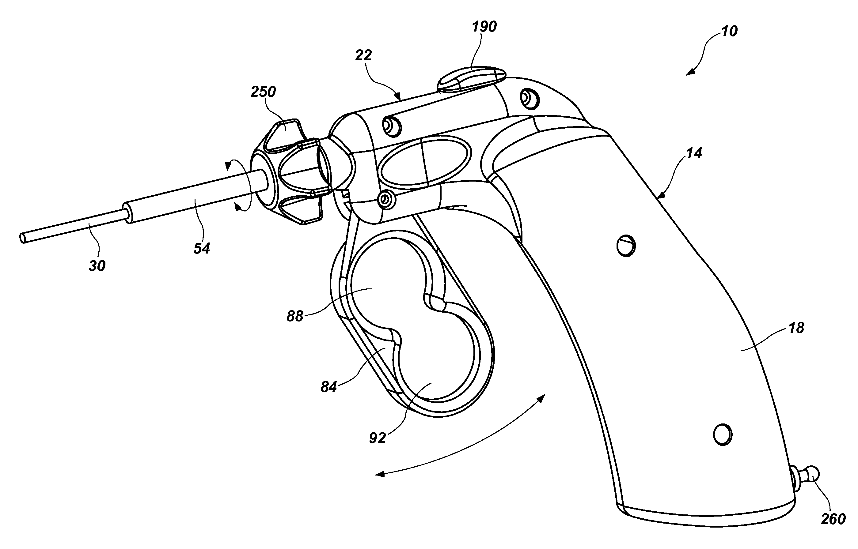
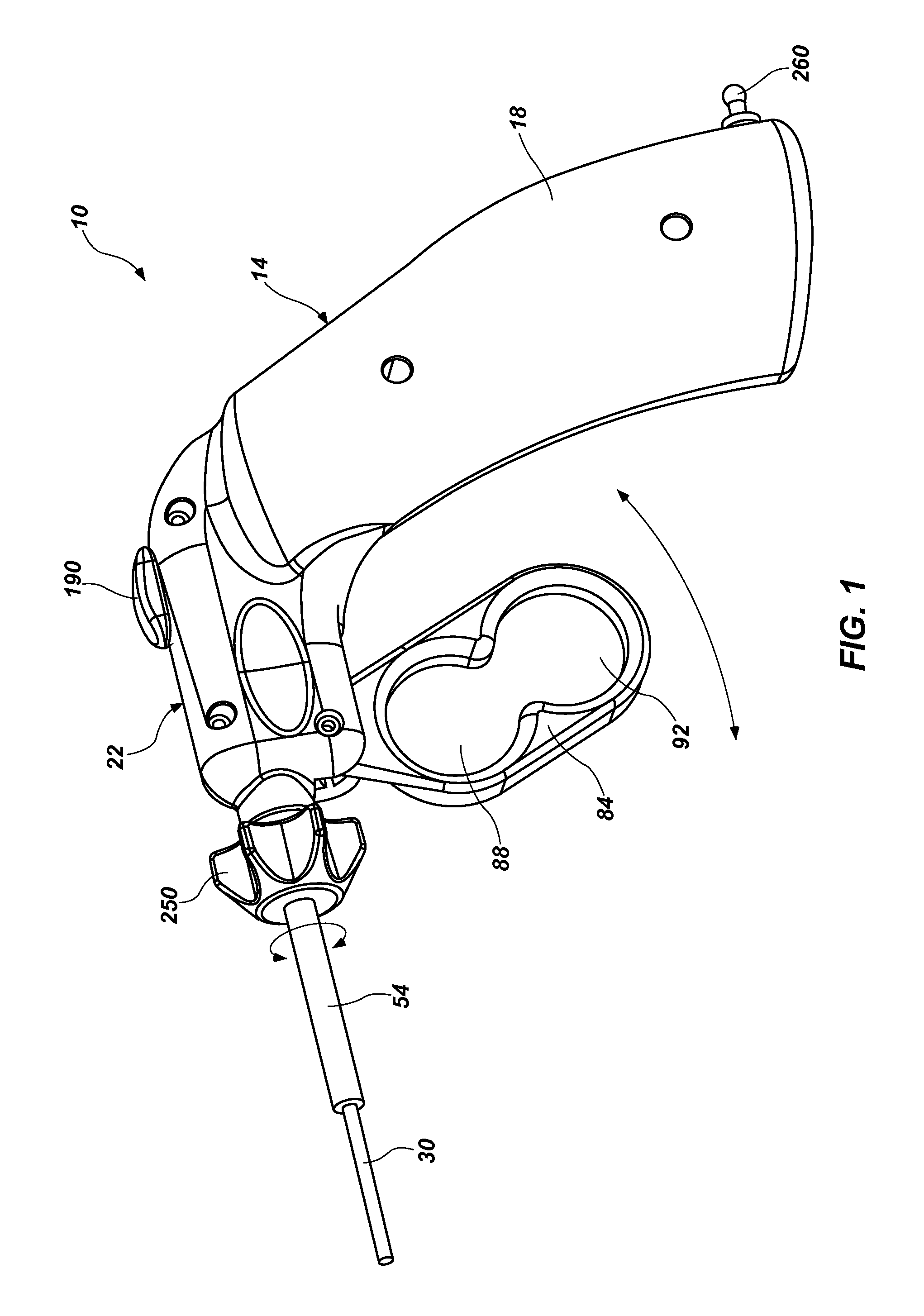
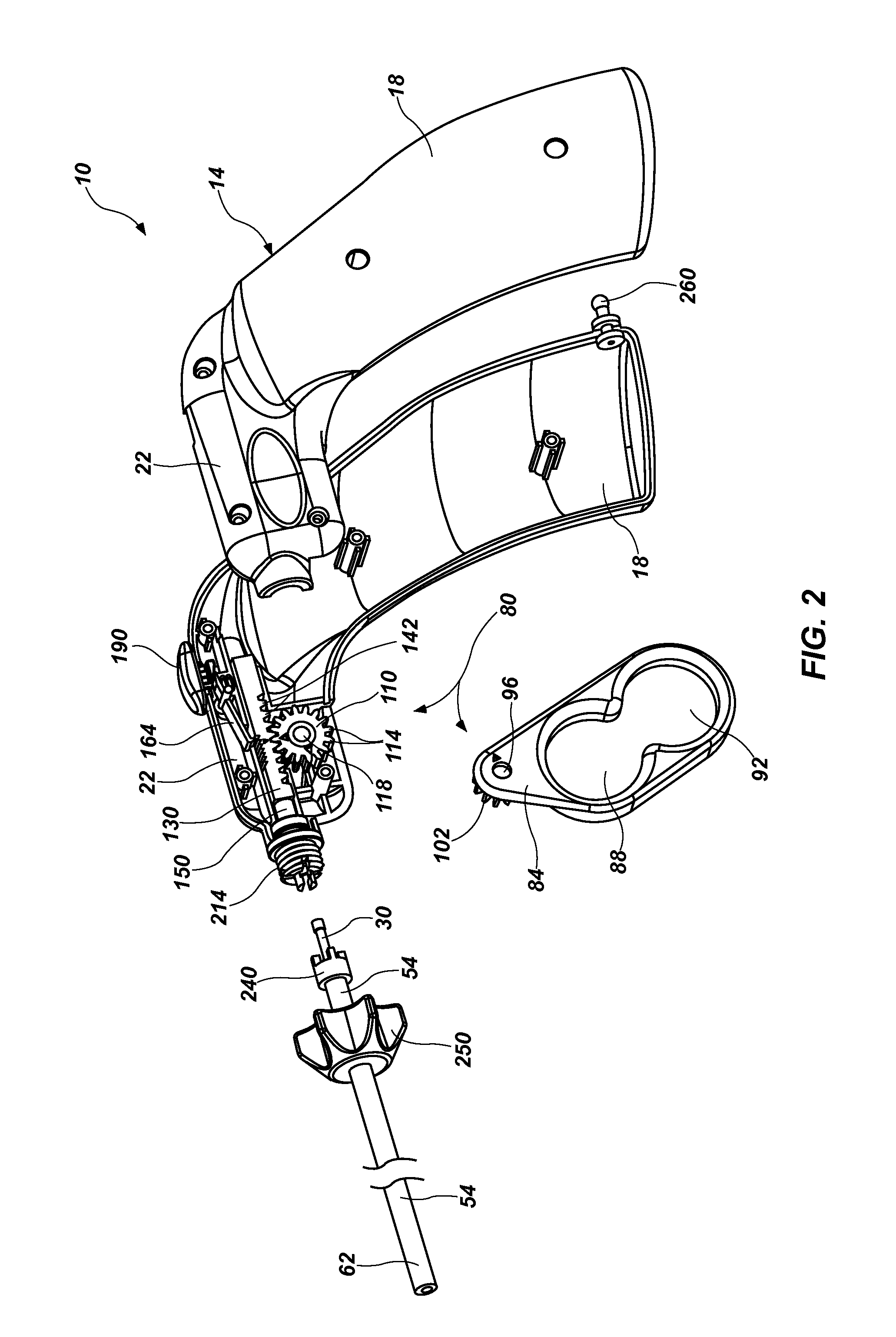
[0017]The following detailed description of exemplary embodiments of the invention makes reference to the accompanying drawings, which form a part hereof and in which are shown, by way of illustration, exemplary embodiments in which the invention may be practiced. While these exemplary embodiments are described in sufficient detail to enable those skilled in the art to practice the invention, it should be understood that other embodiments may be realized and that various changes to the invention may be made without departing from the spirit and scope of the present invention. Thus, the following more detailed description of the embodiments of the present invention, as represented in FIGS. 1 through 5, is not intended to limit the scope of the invention, as claimed, but is presented for purposes of illustration only and not limitation to describe the features and characteristics of the present invention, to set forth the best mode of operation of the invention, and to sufficiently en...


PUM


Abstract

A laparoscopic surgical instrument configured to be ergonomic and anthropometrically correct, the laparoscopic surgical instrument comprising: (a) an ergonomic handle configured to orient a hand of a surgeon in a functional position, the handle comprising a handle grip; (b) an actuating mechanism actuatable by a finger and supported by the handle, the actuating mechanism comprising an actuator shaft and a gearing assembly operable to displace the actuator shaft with a mechanical advantage upon actuation of a trigger by the surgeon; (c) a locking mechanism configured to lock the actuating mechanism in one of a plurality of positions, the locking mechanism comprising a release located in an anthropometrically correct position; and (d) a working shaft having a proximal end coupled to and operable with the actuator shaft, the working shaft having an elongate configuration and a distal working end configured to couple a surgical tool to be manipulated by the surgeon via the handle and the actuating mechanism to perform a surgical function.

Description

FIELD OF THE INVENTION[0001]The present invention relates generally to laparoscopic surgical instruments, and more particularly to a laparoscopic surgical instrument comprising a trigger control system coupled with an ergonomic design for improved usage.BACKGROUND OF THE INVENTION AND RELATED ART[0002]Laparoscopic surgical instruments used for laparoscopic surgery vary significantly in design. Many previous designs for laparoscopic instruments are based on a design that is decades old, a design that was adopted to facilitate their use in upper airway endoscopy. These instruments are bent such that their handles are as much as 90 degrees out of alignment with their functional ends. These instruments were designed primarily to allow the surgeon to achieve a direct line of sight through a sheath and into the area where the instrument was intended to perform a surgical task. Because of this, the instruments were awkward and difficult to use for any extended period of time or for lengthy...

Claims


Application Information

Patent Timeline
Patent Type & Authority Patents(United States)
IPC IPC(8): A61B17/00
CPCA61B17/00234A61B17/2909A61B2017/00407A61B2017/0042A61B2017/00424A61B2017/0046A61B2017/2925A61B2017/2929A61B2017/293A61B2017/2946A61B2017/2923
Inventor DOWNEY, EARLCARTER, STEPHEN B.GROSS, KENNETH A.SCHMUCKLE, DARRIN I.SPLANE, JR., ROBSON L.
Owner SHORTI RAMI
Why Eureka
Try Eureka