Removable anchor and fastener

a technology of a bolt and a bolt is applied in the direction of screws, fastening means, pins, etc., which can solve the problems of difficult or impossible positioning of a nut in such a manner, difficult to hold the nut from turning, and difficulty in fastening a plurality of objects

Inactive Publication Date: 2011-12-27
TERMAX CORP
View PDF42 Cites 71 Cited by
  • Summary
  • Abstract
  • Description
  • Claims
  • Application Information

AI Technical Summary

Problems solved by technology

However, in many industries, as for example in the automobile industry, difficulty is frequently encountered in fastening a plurality of objects together, such as in securing a body panel to the structural framework or chassis because the inside end of the fastening element extends into a cavity that is inaccessible.
As a result, it is difficult or impossible to position a nut in such a manner that a screw can be readily engaged therewith.
Additionally, it is often difficult to hold the nut from turning while the screw is being tightened.
This has often proved disadvantageous because of the impossibility of replacing the nut should it become damaged.
However, this technique also has frequently proved disadvantageous because of the difficulty of removing the fastening device without damage to the members joined by the rivets.
Toggle bolt fasteners do not, however, provide the degree of blind control for the attachment device, coupled with restraint requirements, whereby all types of fastening can be achieved.
Additionally, these devices often utilize complex arrangements for blind attachment, and such arrangements necessarily compromise the strength of the fastener system.
In all cases, however, fasteners currently available, including the toggle bolt fasteners, are not removable, since once the toggle element is rotated, the toggle element is not readily rotated for removal without enlarging or otherwise damaging the hole in the wall.

Method used


Image

  • Removable anchor and fastener
  • Removable anchor and fastener
  • Removable anchor and fastener

Examples


Embodiment Construction

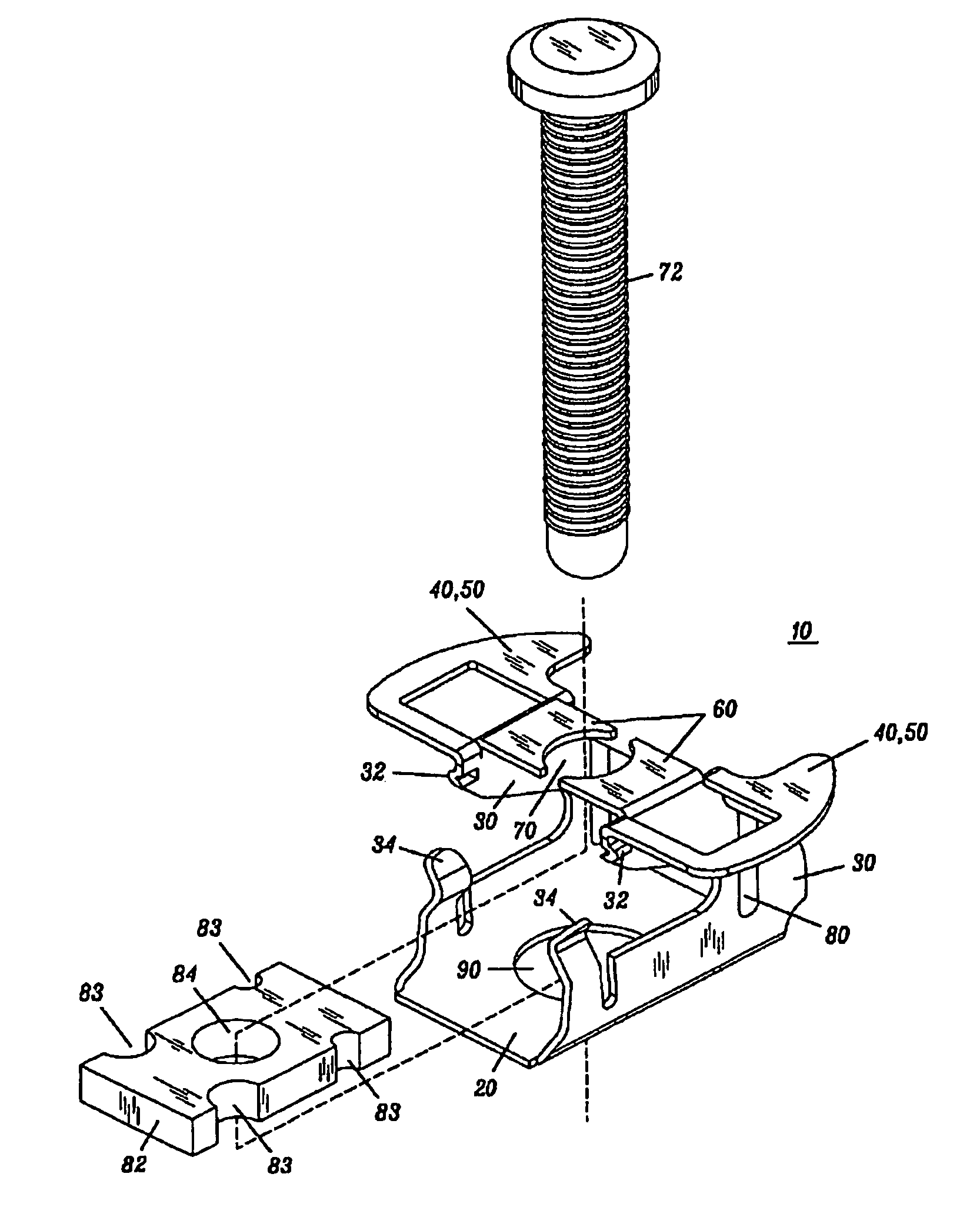
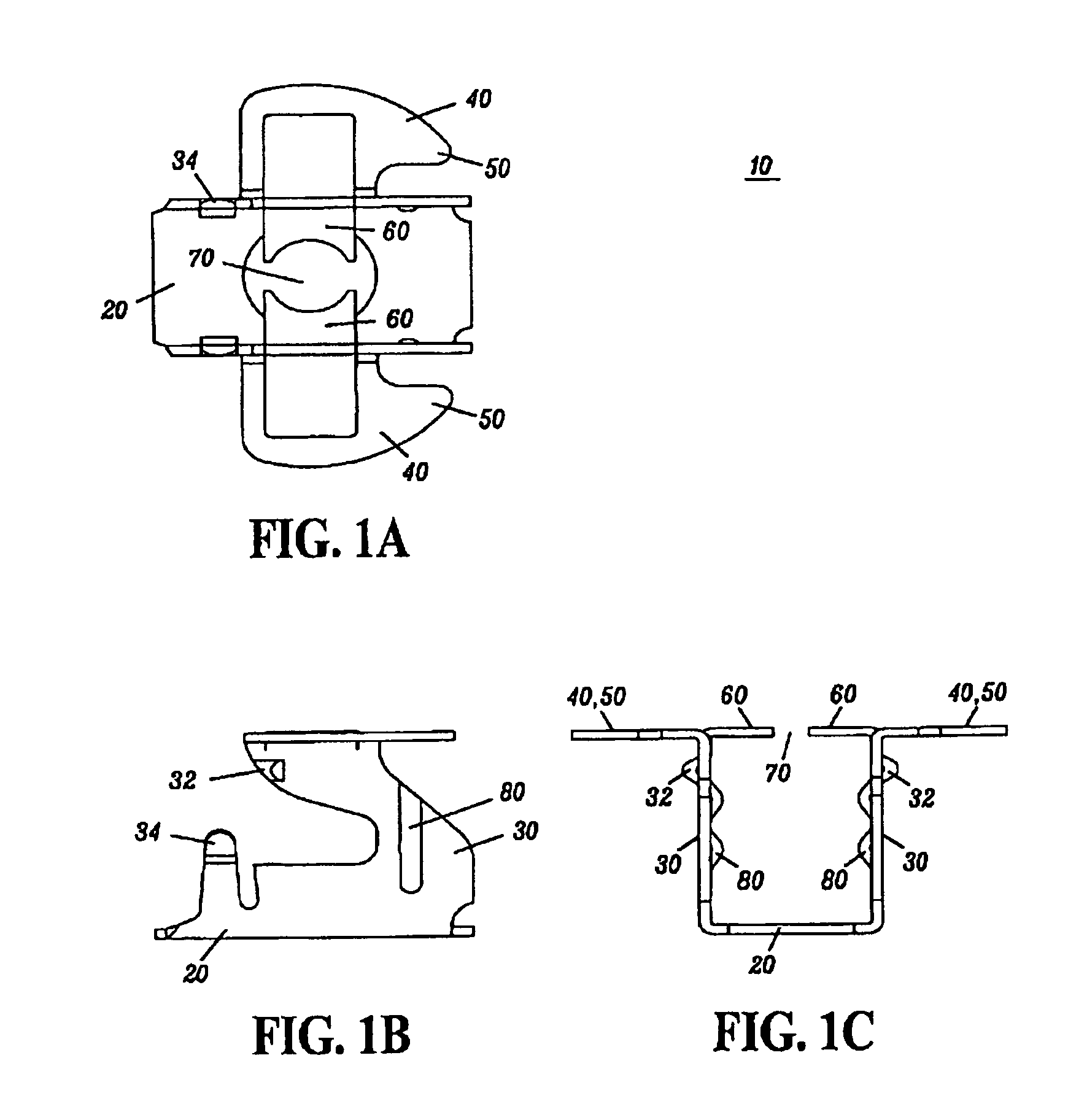
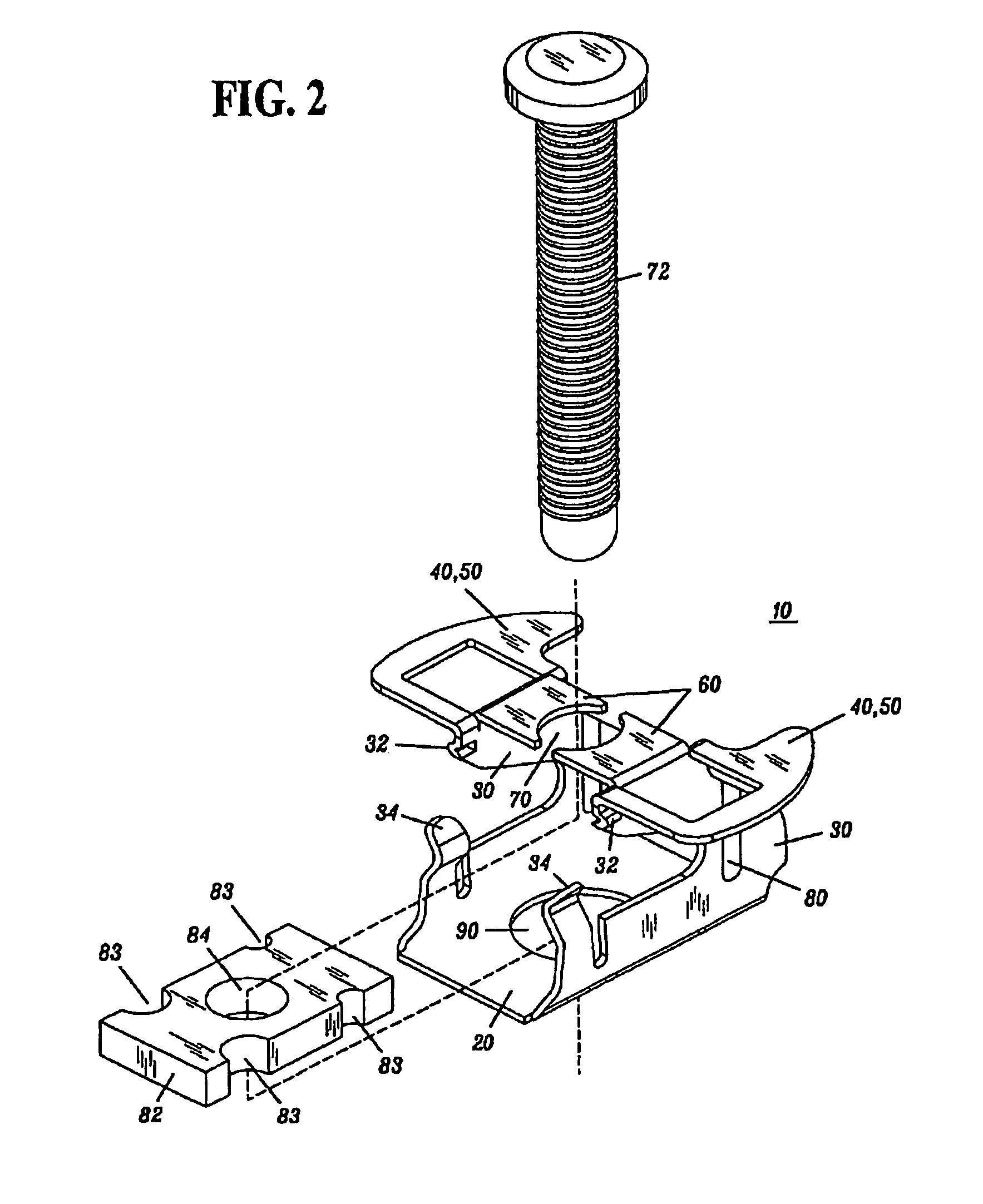
[0014]An anchor facilitates blind engagement by a first fastener in order to connect an object to a hollow substrate. The first fastener may be a bolt, a screw, or any suitable fastener, such as a threaded fastener. The anchor may be inserted into a cavity accessible through a hole defined in the hollow substrate to connect the object to the hollow substrate. The anchor includes a base plate to hold a second fastener such as a nut and a pair of laterally offset arms extending from the base plate, such that each arm includes an engagement structure disposed at a distal end of each arm. The engagement structure includes a collar extending outwardly from each arm for engaging an outer surface, and optionally, an inner surface of the hollow substrate upon insertion of the anchor into the cavity. The engagement structure of each arm cooperatively supports the anchor and complementarily engages the first fastener. Additionally, the engagement structure includes a tang extending inwardly f...


PUM


Abstract

An anchor facilitates blind engagement by a first fastener in order to connect an object to a wall. The anchor may be inserted into a cavity accessible through a hole defined in a hollow substrate to connect the object to the wall. The anchor includes a base plate and a pair of laterally offset arms extending from the base plate, such that each arm includes an engagement structure disposed at a distal end of each arm. The engagement structure of each arm cooperatively supports the anchor and complementarily engages the first fastener. The first fastener may be a bolt, a screw, or any suitable fastener such as a threaded fastener. The engagement structure includes a collar extending outwardly from each arm for engaging the hollow substrate upon insertion of the anchor into the cavity. Additionally, the engagement structure includes a tang extending inwardly from each arm, generally defining a portion of a first aperture for engaging the first fastener.

Description

FIELD OF THE INVENTION[0001]The invention relates generally to anchoring devices for fastening objects, and more particularly to an anchoring device for insertion into a cavity accessible through a hole defined in a hollow substrate, wall, plate, or any suitable planar surface to facilitate blind engagement by a fastener.BACKGROUND OF THE INVENTION[0002]A number of devices and fasteners are currently available for blind attachment of objects to structures such as hollow substrates. As used herein, the attachment of an object to a hollow substrate also refers to the attachment of the object to a hollow substrate, plate, body panel, structural framework, wall or any suitable object. However, in many industries, as for example in the automobile industry, difficulty is frequently encountered in fastening a plurality of objects together, such as in securing a body panel to the structural framework or chassis because the inside end of the fastening element extends into a cavity that is in...

Claims


Application Information

Patent Timeline
Patent Type & Authority Patents(United States)
IPC IPC(8): F16B39/284
CPCF16B37/044F16B37/0842F16B33/002F16B41/002Y10S411/97
Inventor SMITH, MICHAEL WALTERGIUGLIANO, MICHAEL ANTHONYDICKINSON, DANIEL JAMESFLEYDERVISH, MARKSACHA, EDWARD
Owner TERMAX CORP
Why Eureka
Try Eureka