Automatically retractable safety injector for non-liquid material

a safety injector and non-liquid material technology, applied in the field of safety injectors, can solve the problems of increased risk of needlestick injury, difficult and convenient use for healthcare workers, and small dimensional tolerance of molds used to form one-piece plungers through injection molding process, so as to facilitate one-hand operation and eliminate liability for being damaged

Active Publication Date: 2012-01-03
BENCHA INT GROUP
View PDF21 Cites 6 Cited by
  • Summary
  • Abstract
  • Description
  • Claims
  • Application Information

AI Technical Summary

Benefits of technology

[0008]The present invention has been accomplished under these circumstances in view. It is one objective of the present invention to provide a safety injector and a plunger combination thereof which facilitate one-hand operation and eliminate the liability to being damaged during injection operation by a user's inexact force-exerting angle and posture.
[0009]It is another objective of the present invention to provide a safety injector and a plunger combination thereof which eliminate the liability to being damaged during fabrication, for purposes of enhancing the quality and yields rate, improving the reliability, and reducing material waste and processing costs of the disclosed subject matter.
[0010]It is another objective of the present invention to provide a safety injector and a plunger combination thereof which can be easily made through plastic injection molding process, so as to ease the dimensional request for the precision of the molds for producing injectors and rationalize the dimensional tolerance, such that the manufacturing costs of the disclosed subject matter can be reduced.

Problems solved by technology

However, most of such safety syringes are designed to be operated with two hands which is not easy and convenient for healthcare worker to use.
Consequently, the two-handed operated safety syringes are not preferred by the healthcare works, because there are more risks of needlestick injury than one-handed operated safety syringe.
Consequently, the dimensional tolerance for the molds used to form the one-piece plunger through injection molding process is very small.
Besides, the conventional plunger is liable to be broken during fabrication and transportation.
Therefore, the yield rate and output are significantly limited while the costs of molds are unavoidably high.
Further, with the precise design, safety function of retraction of such conventional plunger can only be effective when the plunger is operated at a predetermined force-exerting angle.
Thus, when the prior syringe is implemented to inject a patient at his / her curved-contour skin portion or his / her delicate apparatus, such as the head, postauricular, eyes, or oral skin, it is difficult for a medical staff member to operate the syringe with his / her single hand.
Moreover, clumsy operation due to the limited force-exerting angle can accidentally damage the syringe and cause discomfort to the patient.

Method used


Image

  • Automatically retractable safety injector for non-liquid material
  • Automatically retractable safety injector for non-liquid material
  • Automatically retractable safety injector for non-liquid material

Examples


first embodiment

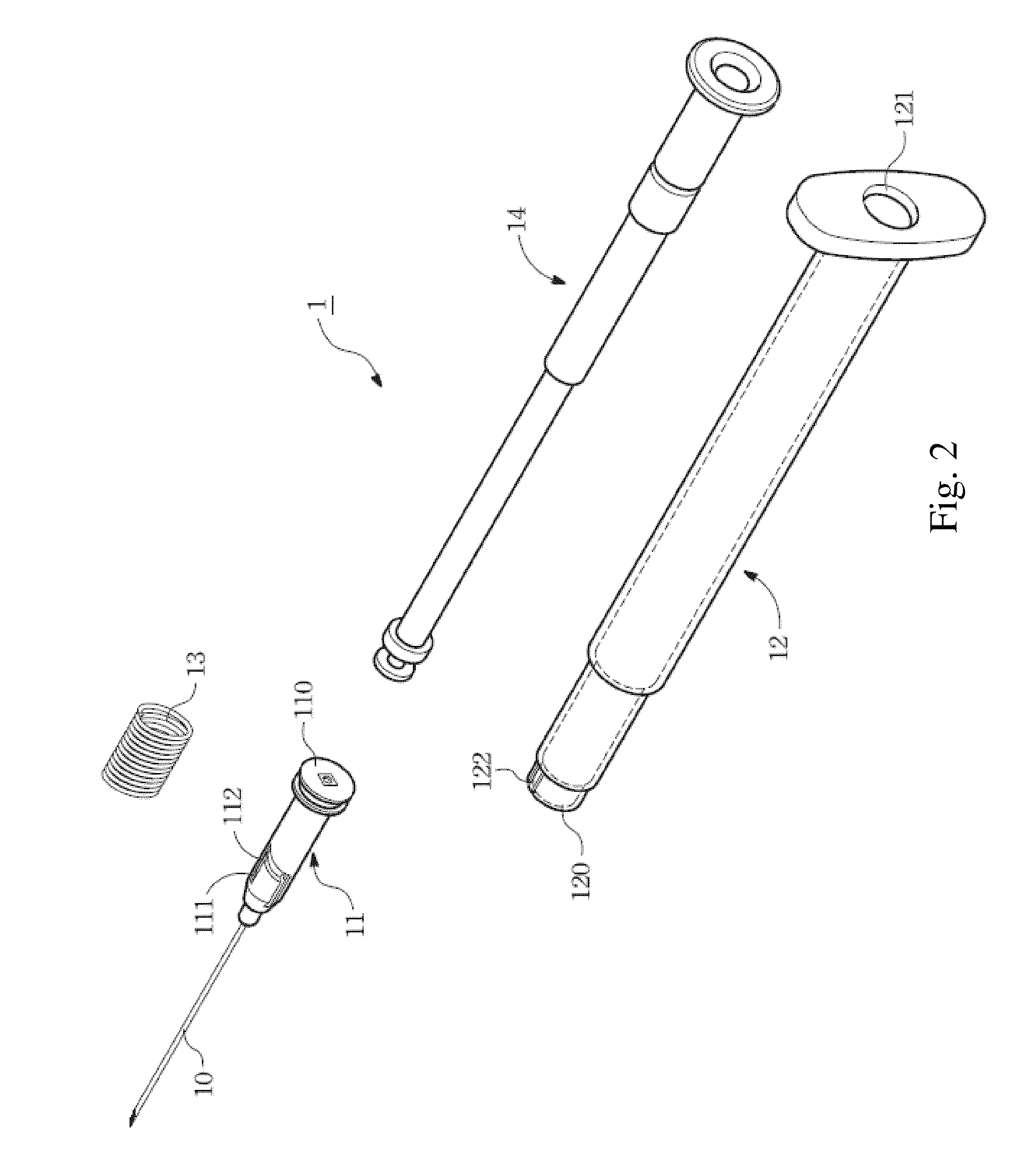
[0059]Referring to FIG. 2, according to the present invention, the disclosed automatically retractable safety injector 1 comprises at lease: a needle hub 11 attached with a needle 10, a hollow barrel 12, and a plunger combination 14 settled in the hollow barrel 12. The hollow barrel 12 engages with the needle hub 11 and at least one annular retracting spring 13 is implemented to guide the needle hub 11 to retract along a direction opposite to a direction where the needle hub moves during injection operation.

[0060]Particularly, the needle hub 11 has one end thereof accommodating the needle 10 that penetrates a center of the needle hub 11 and has an opposite end provided with a disc 110 for receiving the compressed annular retracting spring 13. Pluralities of positioning grooves 111 and U-shaped slide passages 112 contacting the positioning grooves 111 are disposed at proper positions between the two ends of the needle hub 11. The positioning grooves 111 are used to engage with a fron...

fifth embodiment

[0079]In FIG. 10, a safety injector and a plunger combination according to the present invention is illustrated. Therein, a plurality of stoppers 564 are formed at the telescoping portion A and near a lower edge of a depression or a concave annular rib or a annular groove 560 deposited on an inner wall of a hollow plunger 56 along a direction where a retractable plunger 55 retracts. The stoppers 564 contribute to an enhanced counterforce of the retractable plunger 55 during injection operation so that the retractable plunger 55 and the hollow plunger 56 can be combined with enhanced firmness. Therein, the stoppers 564 may be raised portions formed integrally with the hollow plunger 56 through injection molding process or affixed blocks. Further, the stoppers 564 each having an extending surface perpendicular to a lengthwise axis of the hollow plunger 56 or inclined along a direction coordinated to a direction where the retractable plunger 55 retracts.

[0080]In the fifth embodiment, t...

sixth embodiment

[0081]FIG. 12 describes a safety injector and a plunger combination according to the present invention. In the present embodiment, a rough region 655 constructed from, for example, uneven concave grooves and convex ribs, transverse striatures or rough surface with grains, is provided above a raised portion 650 on an outer surface of a retractable plunger 65. The rough region 655 functions for neutralizing or buffing a user's excessive pushing force acting on the plunger combination so as to prevent the retractable plunger 65 from prematurely retracting into the hollow plunger (not shown) before completion of injection operation so that successful injection can be ensured.

[0082]The plunger combination of the automatically retractable safety injector disclosed in the present invention is designed as a two-piece structure. The retractable plunger and the hollow plunger, which are made of a flexible material such as plastic or rubber, are separately molded through injection molding proc...


PUM


Abstract

A safety injector comprises a needle hub attached by a needle, a hollow barrel for engaging with the needle hub and guiding the needle hub to retract into the hollow barrel, and a plunger combination settled in the hollow barrel. The plunger combination comprises a retractable plunger and a hollow plunger partially telescoped with the retractable plunger, wherein at least one raised portion is formed on an outer wall of the retractable plunger and at a telescoping portion for engaging at least one depression formed on an inner wall of the hollow plunger so that when the plunger combination continuously receives a pushing force after the safety injector is used to perform the injection operation, the retractable plunger can smoothly retract into the hollow plunger. Consequently, a space in the hollow barrel can be spared for accommodating the retracted needle hub.

Description

[0001]This application is a continuation-in-part application of, and claims the benefit of priority from, the U.S. patent application Ser. No. 11 / 600,755 filed on Nov. 17, 2006, now U.S. Pat. No. 7,674,21 the contents of which are incorporated by reference.BACKGROUND OF THE INVENTION[0002]1. Technical Field[0003]The present invention relates to safety injectors and, more particularly, to an automatically retractable safety injector and a plunger combination which is one-hand operatable and functions for automatically retracting a needle thereof after the injection is completed to prevent needlestick injury.[0004]2. Description of Related Art[0005]For purposes of avoiding the risk of cross-infection of infectious disease such as AIDS, Hepatitis B, and Hepatitis C; precluding drug addicts from repeatedly using injectors; and protecting medical staff from being accidentally injured by used needles. There are many patents related to so called “safety syringe”. However, most of such safe...

Claims


Application Information

Patent Timeline
Patent Type & Authority Patents(United States)
IPC IPC(8): A61M5/32
CPCA61M5/3234A61M5/5066
Inventor LIN LEE, LEEKUO, MING-TSUNG
Owner BENCHA INT GROUP
Why Eureka
Try Eureka