

Electrical connector lock
a technology of electrical connectors and locking holes, which is applied in the direction of electrical apparatus, coupling device connections, two-pole connections, etc., can solve the problems of unintentional disconnecting of male connectors, difficulty in manipulation, and inability to secure the male connector portion in the housing
- Summary
- Abstract
- Description
- Claims
- Application Information
AI Technical Summary
Benefits of technology
Problems solved by technology
Method used
Image

Examples
first embodiment
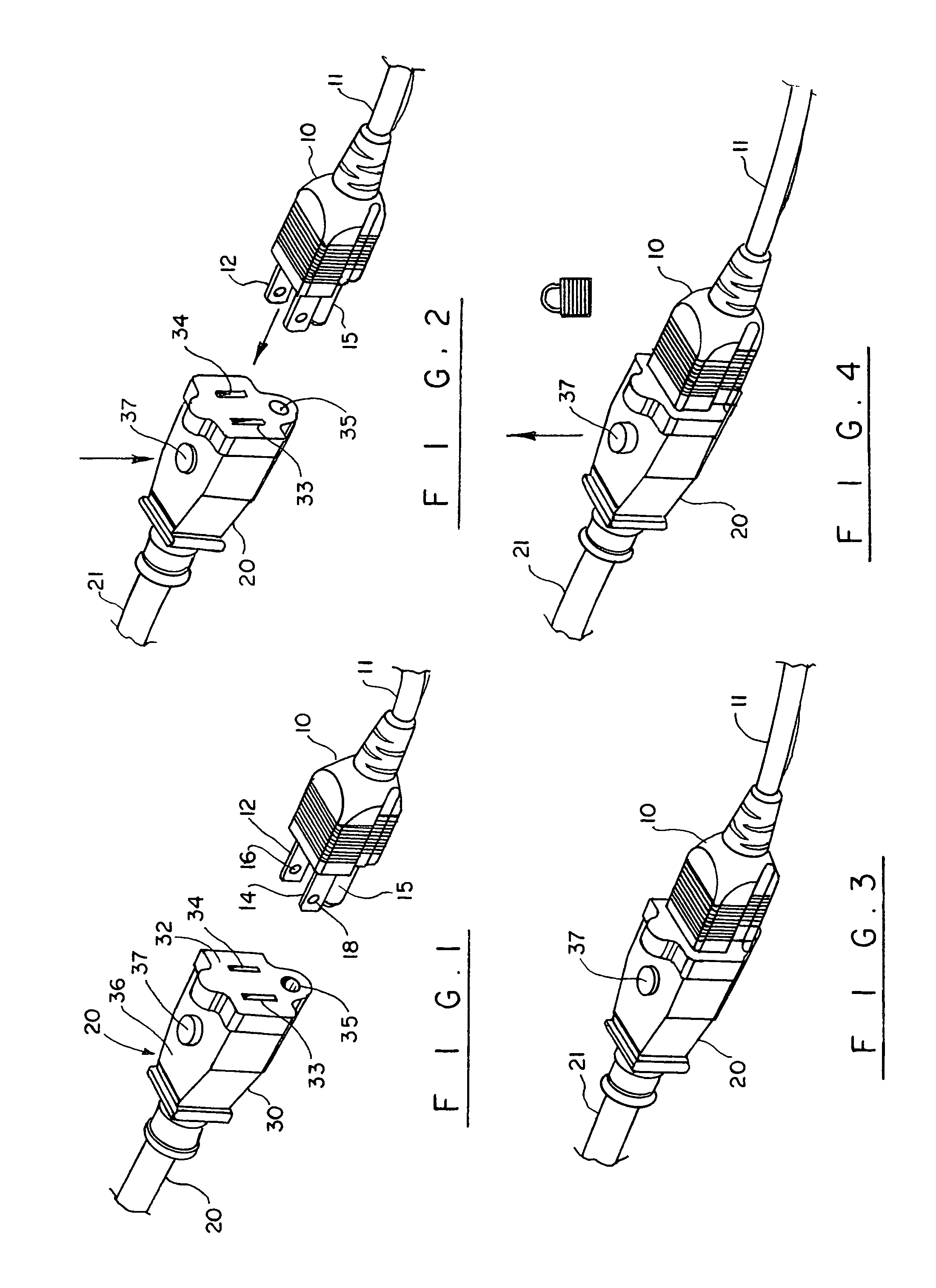
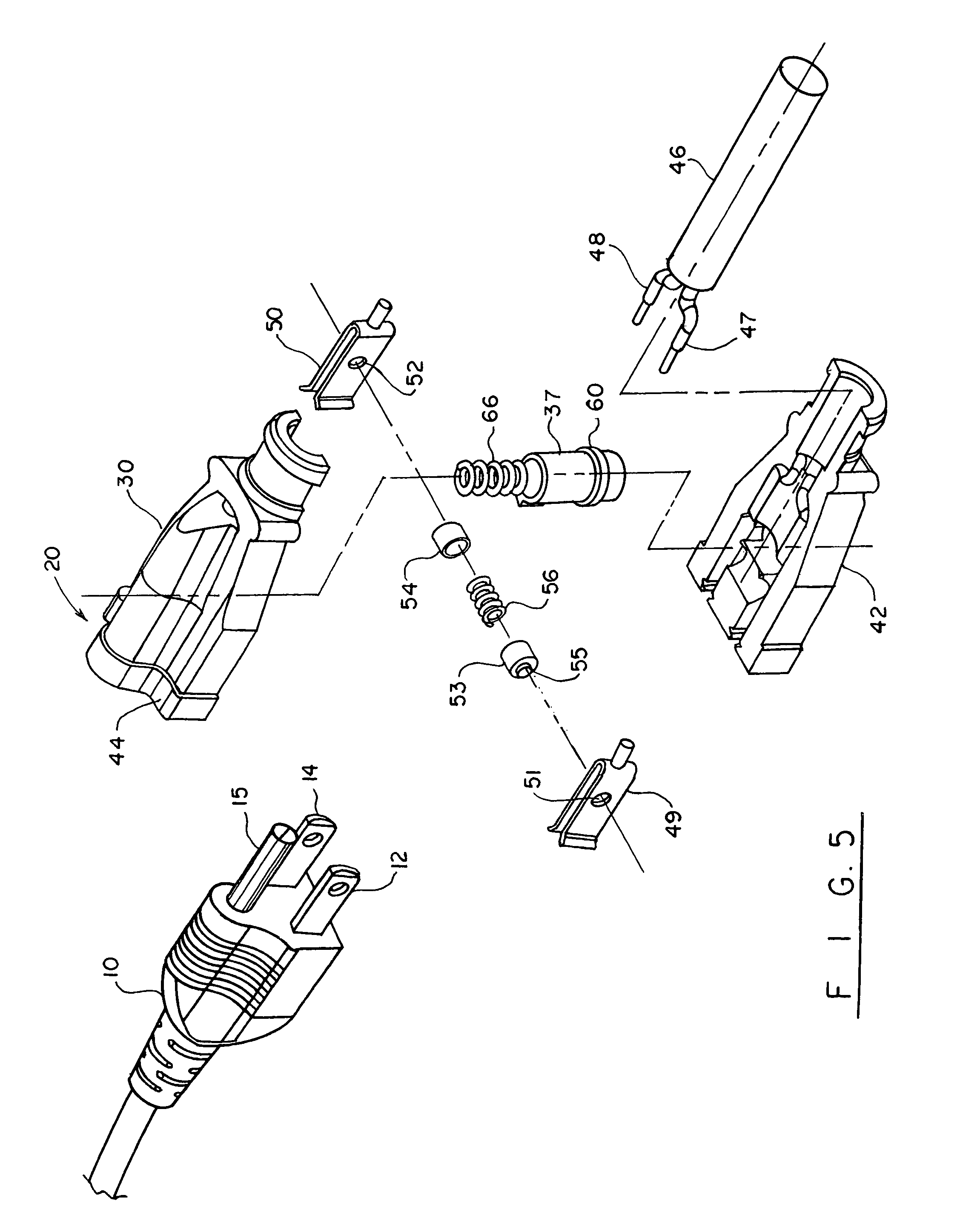
[0035]Turning now to the drawings in more detail, and in particular to FIGS. 1-13, the present invention can be seen in use with an electrical male connector plug 10 having conventional insulated electrical cord 11 and a plurality of outwardly conductive extended prongs 12 and 14, and a ground prong 15. The prongs 12 and 14 contain prong apertures 16 and 18, respectively. The locking assembly of the present invention is configured to lockingly engage the prong apertures 16, 18 when the male electrical cord plug 10 is inserted a predetermined distance within the female receptor 20 and prevent disengagement of the male connector plug 10.
[0036]Electrical female receptor 20 is connected to a typical electrical line or cord 21 having an exterior electrical insulation. The male plug 10 and female receptor 20 can be attached to any conductive electrical lines, such as in connection with extension cords to the insulated cords 11, 21.
[0037]The female receptor 20 is formed as a molded recepto...
second embodiment
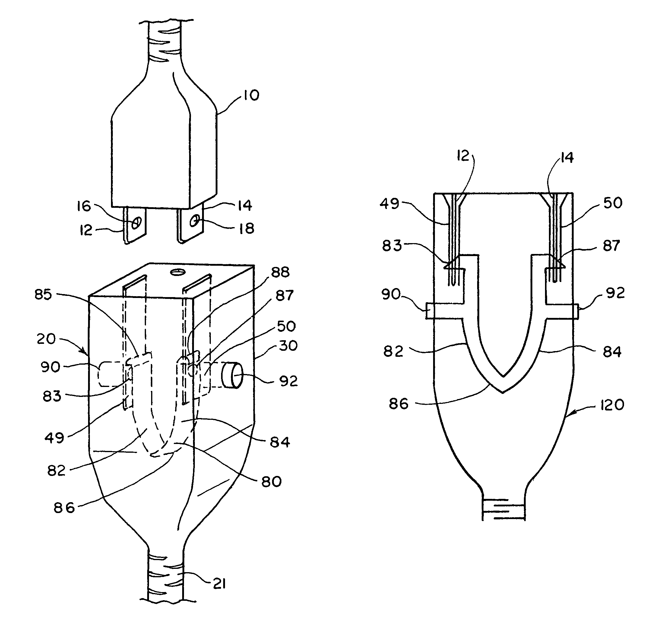
[0047]Turning now to FIGS. 14-17, the locking assembly of the present invention is shown in detail. In this embodiment, a generally U-shaped leaf spring 80 is positioned in the housing 30. The leaf spring 80 comprises a pair of spaced-apart leaf spring portions 82, 84 connected by an arcuate bridge 86. The bridge 86 can have a U-shaped or V-shaped cross-sections and other configurations, depending on the manufacturer's preference and the strength of the leaf spring portions 82, 84.
[0048]A projection 83 is secured adjacent a free end 85 of the leaf spring portion 82. A similar projection 87 is secured adjacent a free end 88 of the second leaf spring portion 84. The free ends of the leaf spring portions 82, 84 extend between the contact members 49, 50. The projections 83 and 83 are sized and configured to extend through openings formed in the contact members 49, 50 and openings 16 and 18 formed in the prongs 12, 14, respectively.
[0049]A pair of depressible actuator buttons 90, 92 is s...
third embodiment
[0052]FIGS. 18 and 19 illustrate the invention, wherein free ends of the leaf spring portions 102, 104 are located outside of the contact members 49, 50 and engage the openings formed in the contact members and the prongs from the outside. Each of the leaf spring portions 102, 104 is provided with a corresponding projection 100, 101.
[0053]Push buttons 106, 107 are secured to the spring leaf portions 102, 104 a distance from the projections 100, 101. In this design, when the actuator buttons 106, 107 are depressed, the projections 100, 101 are forced out of the openings in the prongs 12, 14 and the contact members 49, 50. Release of the push buttons 106, 107 causes the leaf spring portions 102, 104 to return to their normally tensed position on opposite sides of the contact members 49, 50. In this position, the projections 100, 101 enter through the openings formed in the contact members 49, 50 and the prongs 12, 14, locking the male plug with the female receptor.
[0054]FIGS. 20, 21 i...
PUM
 Abstract
Description
Claims
Application Information