Flow-control supports for distributor plates in composite pressure vessel assemblies

a distributor plate and distributor plate technology, which is applied in the direction of separation process, liquid handling, filtration separation, etc., can solve the problems of so as to avoid damage to the building structure, and affecting the sealing effect of the valve assembly

Active Publication Date: 2012-02-07
ENPRESS
View PDF18 Cites 29 Cited by
  • Summary
  • Abstract
  • Description
  • Claims
  • Application Information

AI Technical Summary

Benefits of technology

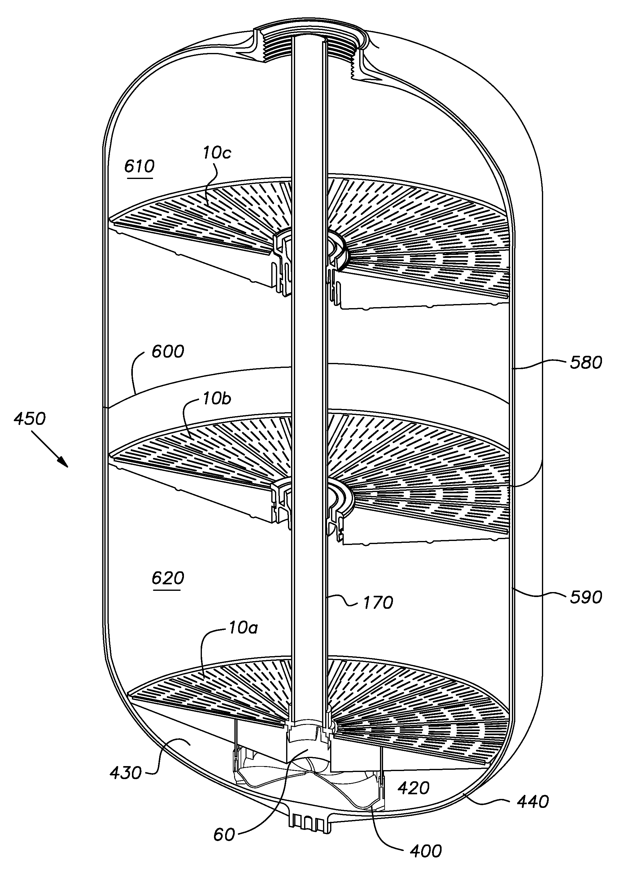
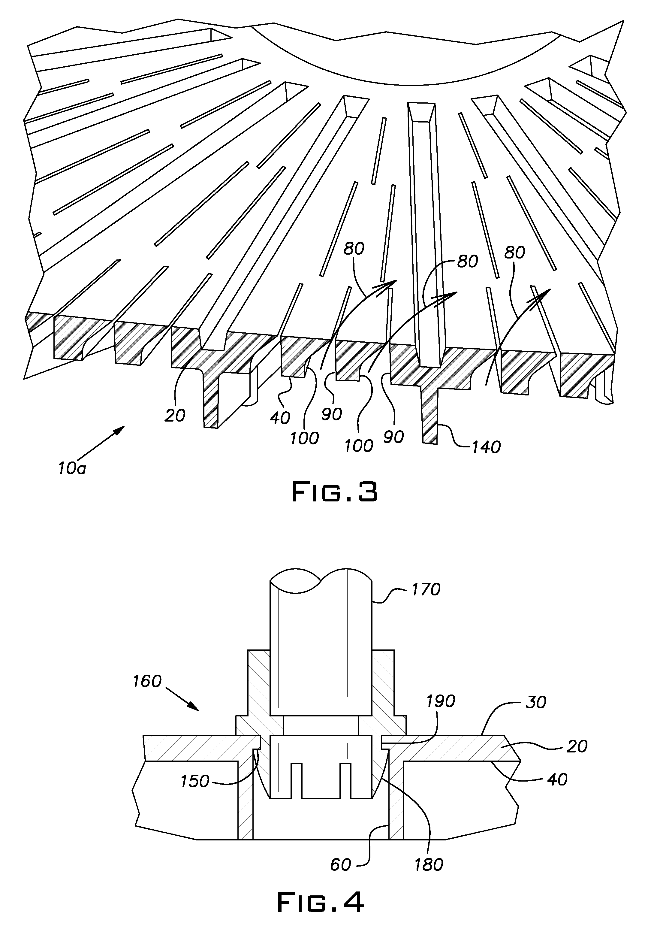
[0009]The present invention provides a flow-control support for a distributor plate in a composite pressure vessel. The distributor plate comprises a thermoplastic polymeric disk having a top side, a bottom side, a perimeter edge and a central opening. In a preferred embodiment, the disk is provided with a plurality of radial slits, which define fluid flow passages through the disk between the central opening and the perimeter edge. The fluid flow passages through the disk are adapted to swirl fluid flowing through the disk such that it swirls around the central opening. The flow-control support is disposed between the bottom side of the distributor plate and an inner side of an end of a thermoplastic liner assembly. The flow-control support includes a spirally fluted upper surface that is adapted to direct fluid flowing from a supply pipe disposed in the central opening of a distributor plate that is supported by the flow control support such that the fluid swirls in a space between the bottom side of the distributor plate and an inner side of an end portion of a water treatment vessel. The swirling water insures that fluid is distributed to substantially all of the fluid flow passages through the disk. This can be highly advantageous, particularly during water treatment media backwashing operations.

Problems solved by technology

In many cases, removal of the valve assembly disturbs the position of the dip tube.
Water treatment media can settle beneath the disturbed distributor basket, making it difficult to re-secure the valve assembly to the top end of the composite pressure vessel and thus close the aperture.
Water pumped into the opened composite pressure vessel during this procedure flows out of the composite pressure vessel and onto the floor, where it creates a mess that can cause damage to the building structure in which the composite pressure vessel is installed.
It also disturbs the water treatment media within the composite pressure vessel, which can adversely affect future water treatment performance.

Method used


Image

  • Flow-control supports for distributor plates in composite pressure vessel assemblies
  • Flow-control supports for distributor plates in composite pressure vessel assemblies
  • Flow-control supports for distributor plates in composite pressure vessel assemblies

Examples


Embodiment Construction

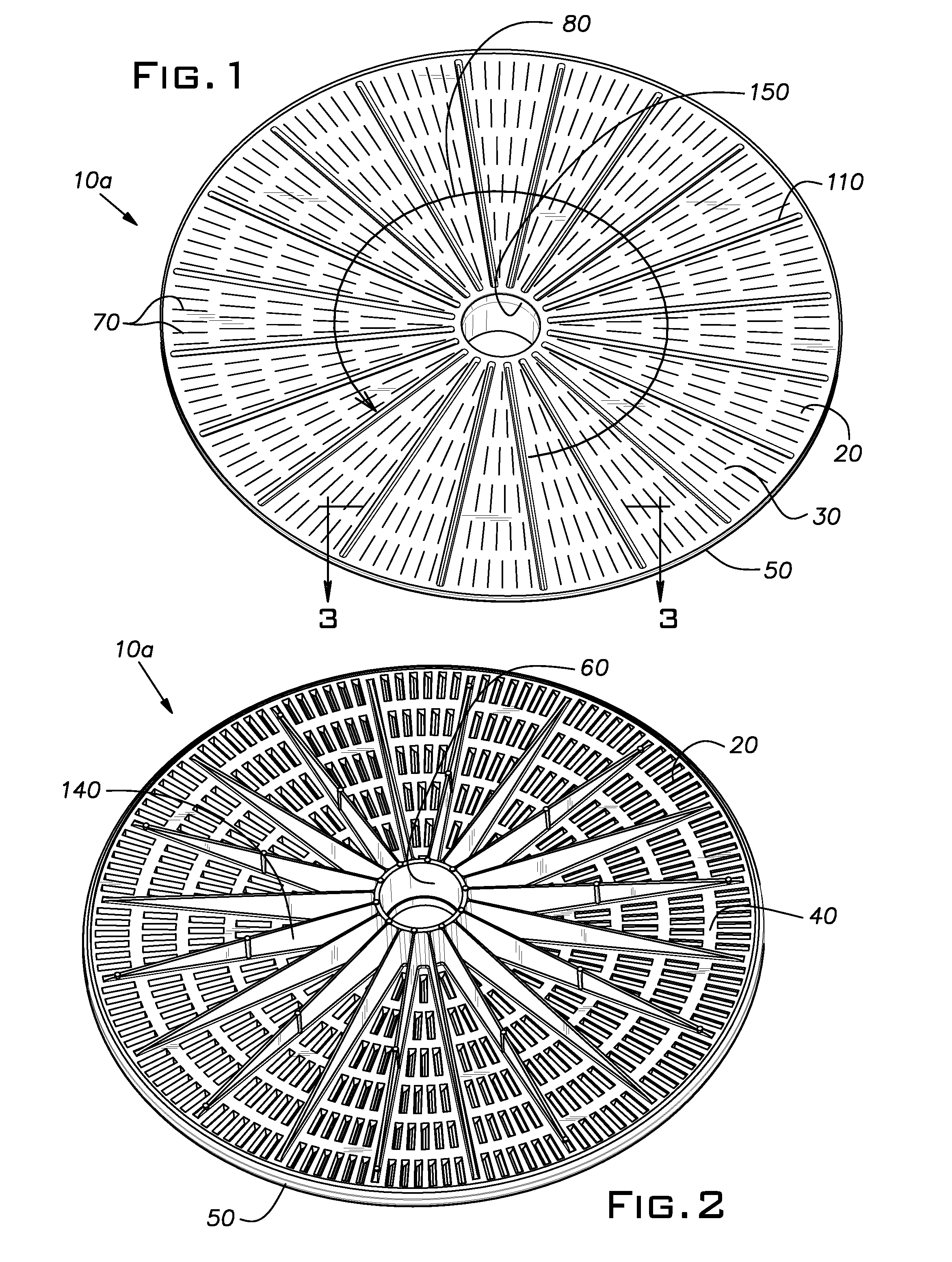
[0025]FIGS. 1-3 show views of an exemplary distributor plate 10a for a composite pressure vessel. The distributor plate 10a comprises a thermoplastic polymeric disk 20 having a top side 30, a bottom side 40, a perimeter edge 50 and a central opening 60. Fluid flow passages must be provided through the disk 20 to allow fluid to pass from the top side 30 to the bottom side 40 through the disk 20 and vice versa.

[0026]In the embodiment illustrated in FIGS. 1-3, radial slits 70 are formed in the disk 20 to define fluid flow passages through the disk 20 between the central opening 60 and the perimeter edge 50. The radial slits 70 are arranged in a plurality of concentric rings around the circumference of the central opening 60. The width of the radial slits 70 at the top side 30 of the disk 20 is not per se critical, but will be selected in view of the size of the water treatment media to be supported on the distributor plate 10a. Radial slits 70 having a width at the top side 30 of the d...


PUM

PropertyMeasurementUnit
timeaaaaaaaaaa
perimeteraaaaaaaaaa
pressureaaaaaaaaaa

Abstract

The present invention provides a flow-control support for a distributor plate in a composite pressure vessel. The distributor plate includes a thermoplastic polymeric disk having a top side, a bottom side, a perimeter edge and a central opening and a plurality of fluid flow passages through the disk. The flow-control support is disposed between the bottom side of the disk and an inner side of an end of a thermoplastic liner assembly. The flow-control support includes a spirally fluted upper surface that is adapted to direct fluid flowing from a supply pipe disposed in the central opening of a distributor plate that is supported by the flow control support such that the fluid swirls in a space between the bottom side of the distributor plate and an inner side of an end portion of a water treatment vessel. The swirling water insures that fluid is distributed to substantially all of the fluid flow passages through the disk during backwashing operations.

Description

CROSS-REFERENCE TO RELATED APPLICATIONS[0001]This application is a continuation-in-part of U.S. application Ser. No. 11 / 834,151, filed Aug. 6, 2007, now U.S. Pat. No. 7,901,576.BACKGROUND OF INVENTION[0002]1. Field of Invention[0003]The present invention relates to flow-control supports for distributor plates in composite pressure vessels, composite pressure vessels that include a flow-control support, methods for manufacturing composite pressure vessels and methods for preparing composite pressure vessels for use in water treatment applications.[0004]2. Description of Related Art[0005]Composite pressure vessels are used in a variety of applications including, for example, in the treatment and / or conditioning of water (e.g., water softeners). Composite pressure vessels used in such applications typically comprise an elongate thermoplastic liner or tank that has been over-wrapped with a reinforcing layer. The elongate thermoplastic liner is typically formed of one or more olefin poly...

Claims


Application Information

Patent Timeline
Patent Type & Authority Patents(United States)
IPC IPC(8): B01D24/12B01D24/46
CPCC02F1/42
Inventor MORMINO, MICHAEL P.STOLARIK, DOUGLAS S.MEST, RICHARD A.HORNER, DOUGLAS M.
Owner ENPRESS
Why Eureka
Try Eureka