Development device and image forming apparatus

a technology of development device and image forming apparatus, which is applied in the direction of electrographic process apparatus, instruments, optics, etc., can solve the problems of increasing the difficulty of dealing with such a toner, increasing the amount of toner to be discarded, etc., and achieves the effect of reducing space and reducing the size of the image forming apparatus

Active Publication Date: 2012-02-14
OKI DATA CORP
View PDF6 Cites 26 Cited by
  • Summary
  • Abstract
  • Description
  • Claims
  • Application Information

AI Technical Summary

Benefits of technology

[0010]Accordingly, the present invention provides a development device and an image forming apparatus capable of reducing a size of the image forming apparatus as a whole by reducing space between each of the development units.

Problems solved by technology

For example, in a case where the conventional image forming apparatus employs a method using a transfer belt or an intermediate transfer belt in a transfer device, a toner adhered to a surface of such a belt is collected as the waste toner in the waste toner container, causing not only an increase in an amount to the toner to be discarded, but also an increase in difficulty of dealing with such a toner.

Method used


Image

  • Development device and image forming apparatus
  • Development device and image forming apparatus
  • Development device and image forming apparatus

Examples


first embodiment

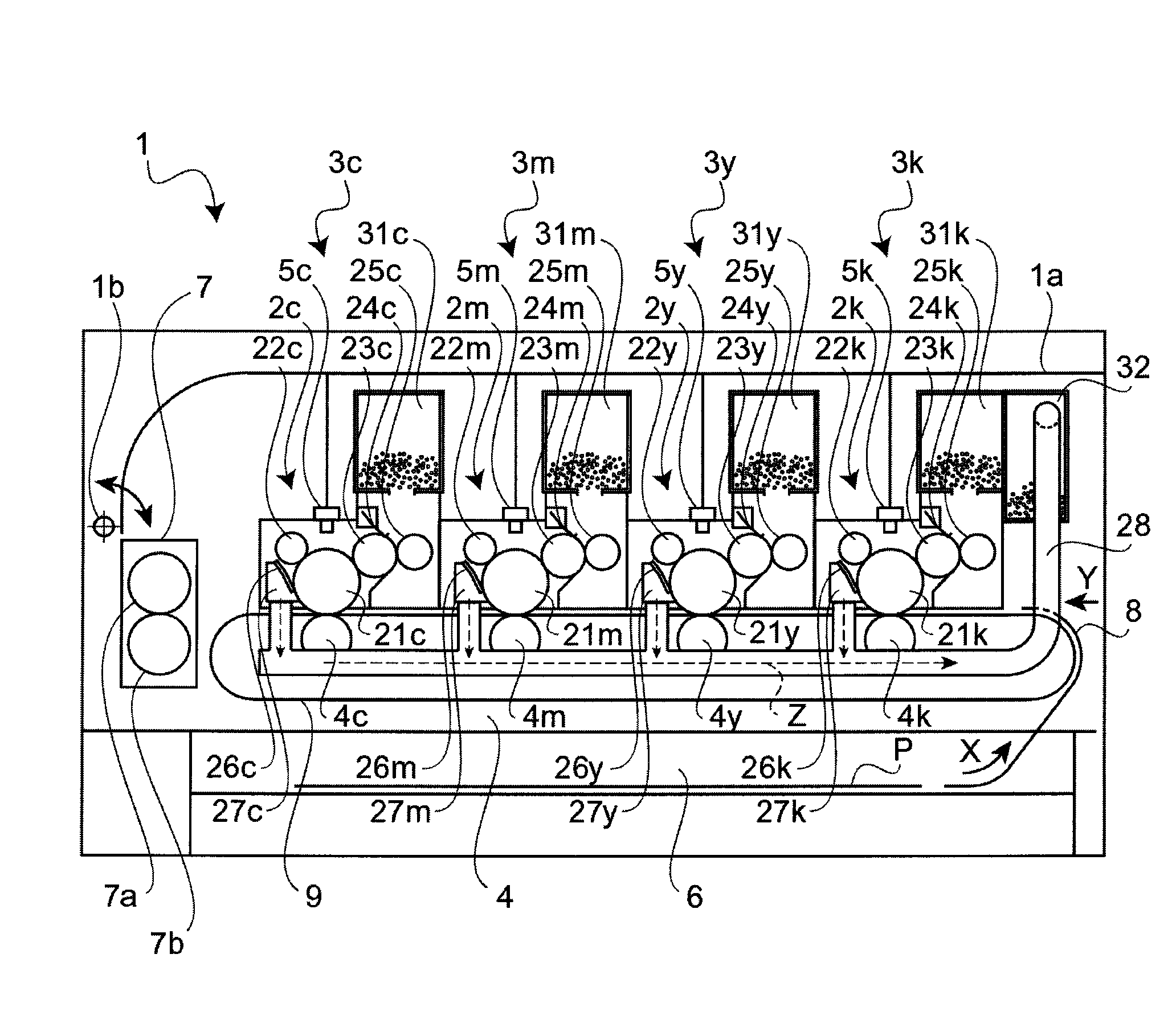
[0029]Referring to FIG. 1, a printer 1 serving as an image forming apparatus according to a first embodiment of the present invention is illustrated. The printer 1 includes: development units 2k, 2y, 2m, and 2c corresponding to toners of black, yellow, magenta, and cyan, respectively (hereafter, the toner colors of black, yellow, magenta, and cyan are abbreviated as k, y, m, and c, respectively); toner cartridges 3k, 3y, 3m, and 3c serving as developer containers storing respective colors of the toner serving as developer; a transfer unit 4 transferring toner images developed on photosensitive drum 21k, 21y, 21m, and 21c (described later) to a sheet P serving as a transfer medium; exposure units 5k, 5y, 5m, and 5c forming electrostatic latent images on surfaces of the photosensitive drums 21k, 21y, 21m, and 21c with irradiation of light; a sheet feeding cassette 6 storing the sheet P therein and feeding the sheet P in a direction indicated by an arrow “X” shown in FIG. 1; a fixing u...

second embodiment

[0080]A printer 100 and image forming operation according to a second embodiment are substantially similar to the printer 1 and image forming operation described above according to the first embodiment. Components and configurations of the printer 100 that differ from those of the above embodiment are described, and like components are given the same reference numerals as above and description thereof are omitted for the sake of simplicity.

[0081]Referring to FIG. 11, a vicinity of a waste toner outlet 285 in a second conveyance member 81 is illustrated in a partial schematic diagram. The second conveyance member 81 includes: a conveyance flat spiral 812 conveying a waste toner; and a drive transmission member 813 (including the drive transmission members 813a, 813b, 813c) transmitting driving force from a drive member (described later) to the conveyance flat spiral 812. Herein, the conveyance flat spiral 812, for example, represents a spiral formed by a wire rod having a flat surfac...


PUM


Abstract

A development device includes a plurality of development units and a waste substance container or containers storing the waste substance removed by the cleaning member. Each of the plural development units includes an image carrier carrying a developer image formed by developer and a cleaning member cleaning the image carrier by removing a waste substance. A number of the waste substance containers disposed is smaller than a number of development units disposed, and the number of the waste substance containers is greater than or equal to one.

Description

BACKGROUND OF THE INVENTION[0001]1. Field of the Invention[0002]The present invention relates to a development device and an image forming apparatus such as a photocopier, a printer, and a facsimile machine with a multicolor electrophotographic method.[0003]2. Description of Related Art[0004]In a conventional image forming apparatus having a plurality of development devices with a multicolor electrophotographic method, a toner is transferred to a transfer medium in the course of image formation while a toner not transferred to the transfer medium is collected as a waste toner by a cleaning device. The waste toner collected by the cleaning device is mixed of different colors of toners. Consequently, the collected toner is discarded without subjecting to recycling.[0005]Generally, a conventional image forming apparatus includes a waste toner container storing a waste toner therein. For example, in a case where the conventional image forming apparatus employs a method using a transfer ...

Claims


Application Information

Patent Timeline
Patent Type & Authority Patents(United States)
IPC IPC(8): G03G15/08
CPCG03G21/12G03G21/105G03G2221/1624
Inventor OHTA, ATSUSHI
Owner OKI DATA CORP
Why Eureka
Try Eureka