AI technical title is built by Patsnap AI team. It summarizes the technical point description of the patent document.
a technology of imaging apparatus and spherical tube, which is applied in the field of imaging apparatus, can solve problems such as and achieve the effect of facilitating reducing the size of imaging apparatus
Inactive Publication Date: 2006-10-03
SONY CORP
View PDF4 Cites 25 Cited by
Summary
Abstract
Description
Claims
Application Information
AI Technical Summary
This helps you quickly interpret patents by identifying the three key elements:
Problems solved by technology
Method used
Benefits of technology
Benefits of technology
This configuration enables a compact imaging apparatus with reduced power consumption and extended battery life, facilitating size reduction and efficient image projection.
Problems solved by technology
Thus, some space inside the imaging apparatus is occupied by the cooling fan, hindering reduction in the size of the imaging apparatus.
Method used
Image
Click on the blue label to locate the original text in one second.
Reading with bidirectional positioning of images and text.
Examples
first embodiment
[0015]There will be described the invention, by reference to FIGS. 1 and 2.
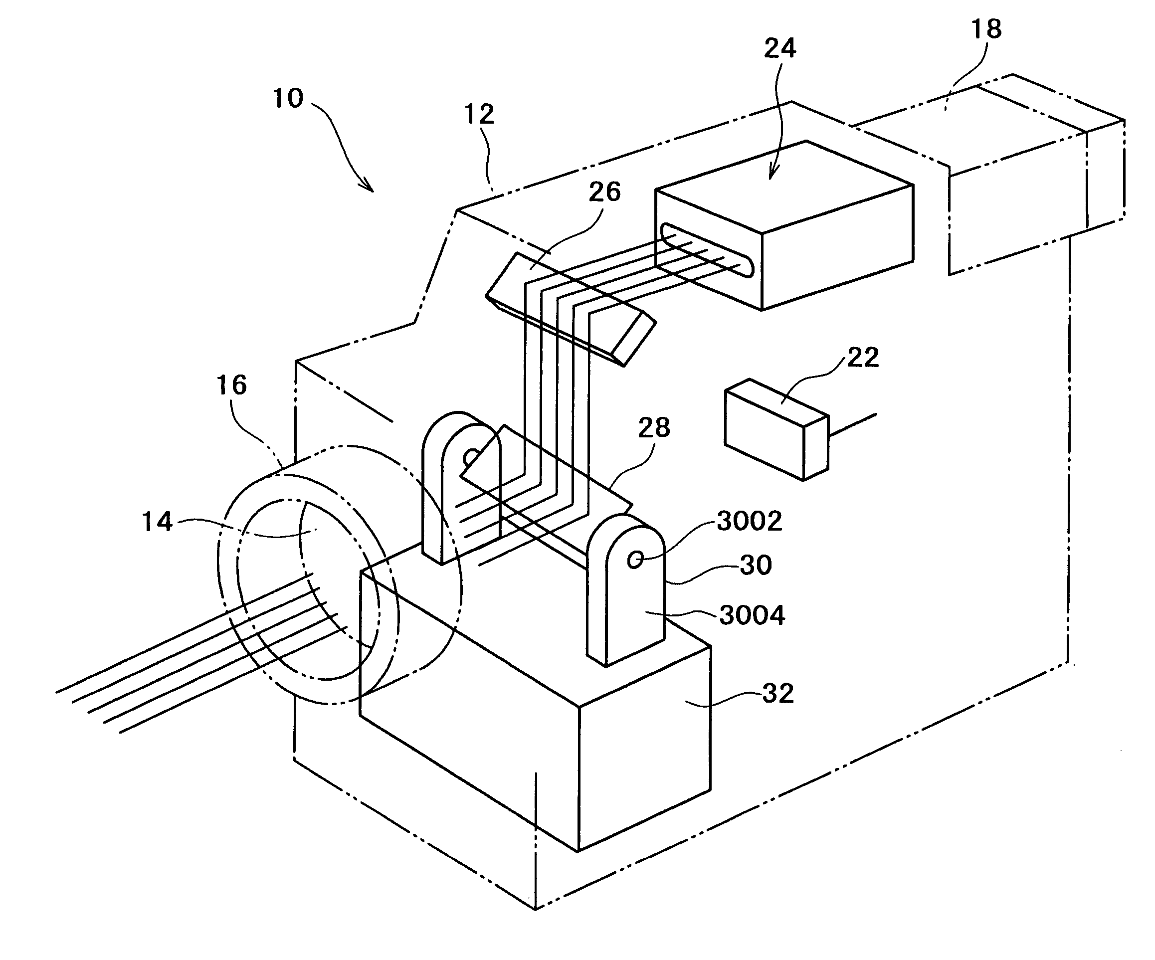
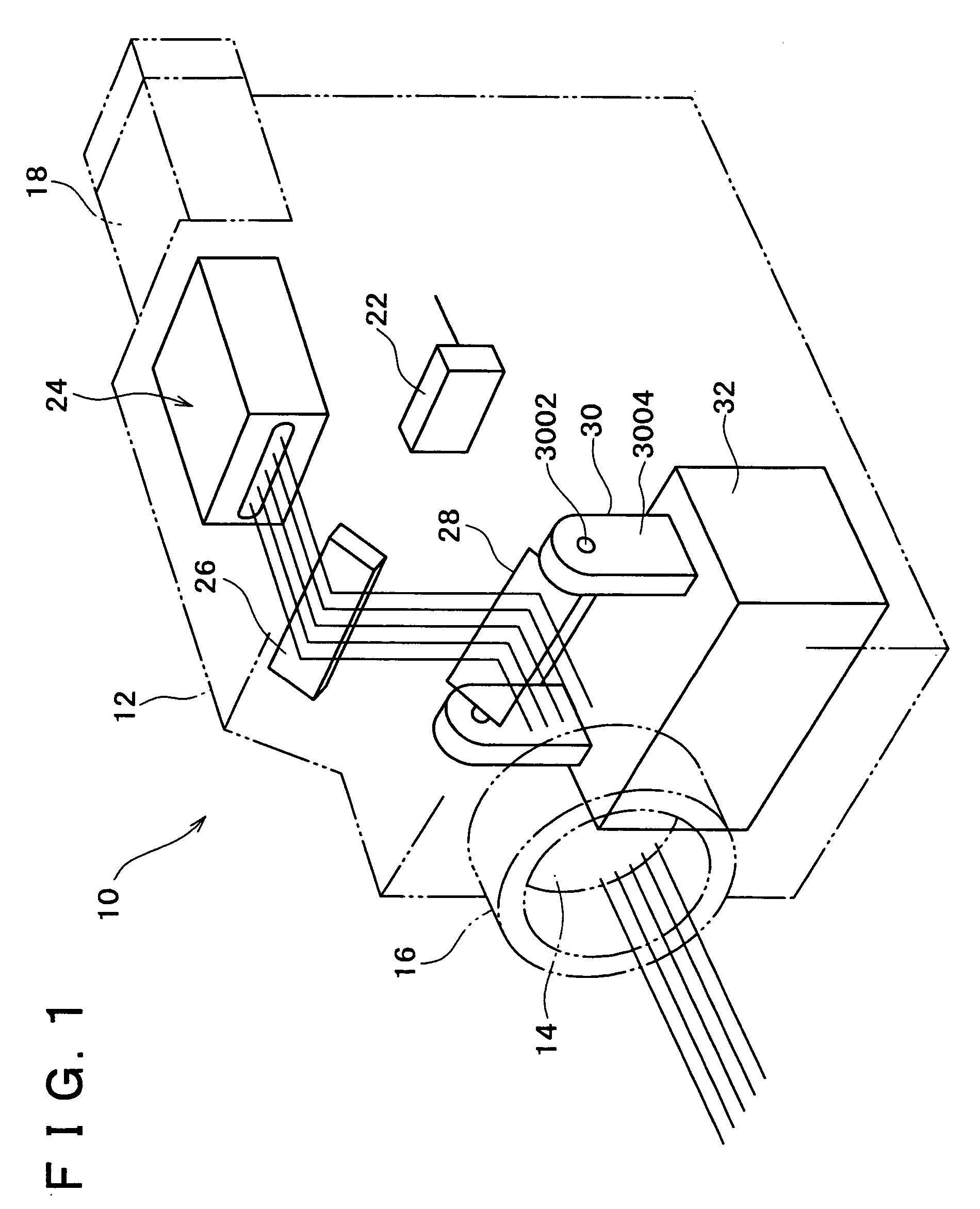
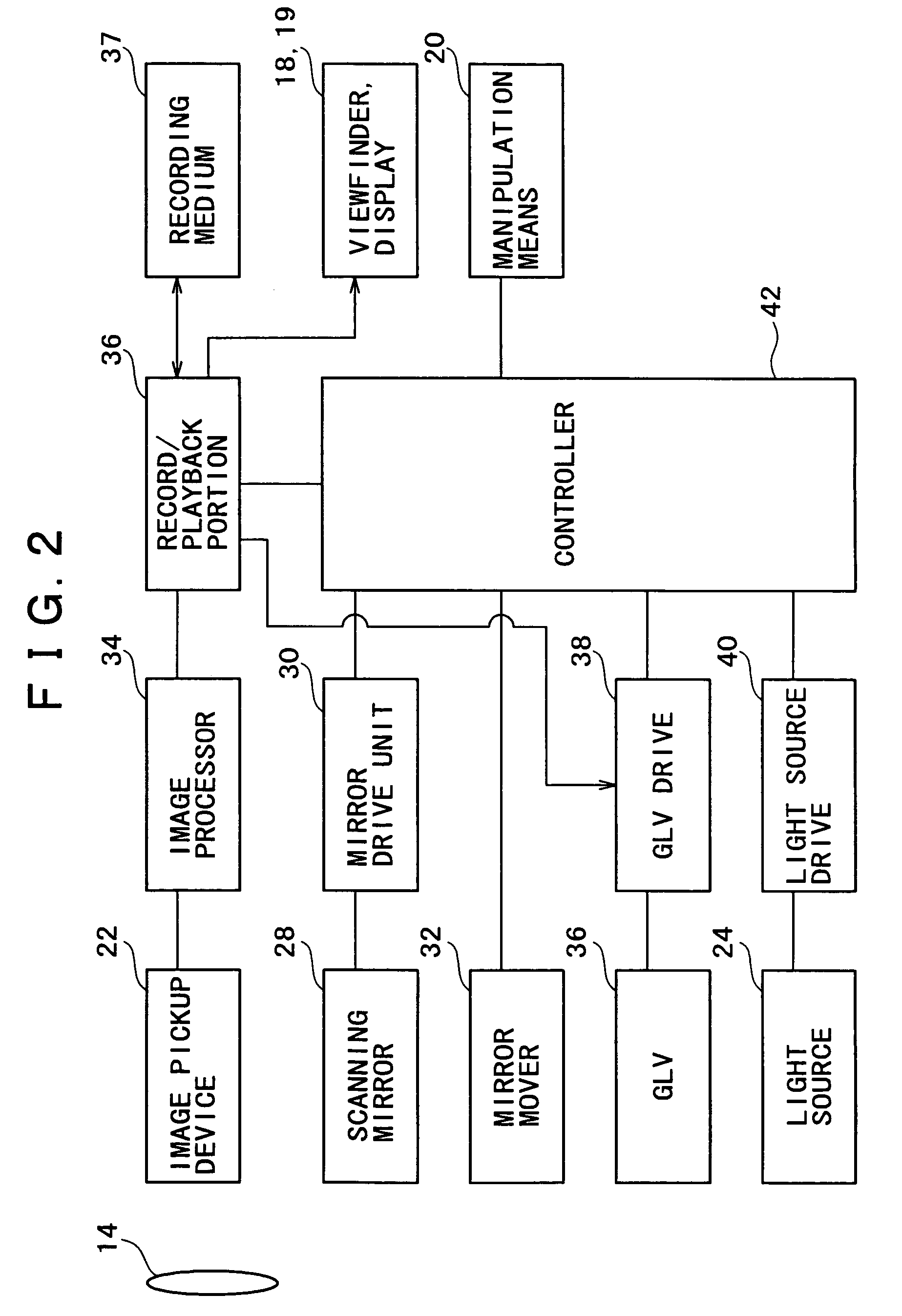
[0016]FIG. 1 is a perspective view showing a structure of an imaging apparatus 10 according to the first embodiment, while FIG. 2 is a block diagram showing the structure of the imaging apparatus 10.
[0017]As shown in FIG. 1, the imaging apparatus 10 is a video camera having a housing 12.
[0018]In the upper part of the front face of the housing 12, there is disposed a lens barrel 16 holding a taking lens 14, while in the upper part of the rear side of the housing 12 is disposed a viewfinder 18 having a liquid crystal display or the like.
[0019]On the lateral faces of the housing 12, there is disposed manipulation means 20 (indicated in FIG. 2) including an ON / OFF button, a shutter / video button, a play button and a mode button. The mode button is manipulated or switched for selecting whether the video camera 10 is to be operated as a usual video camera or as a projector.
[0020]A display 19 (indicated in FIG. 2), w...
second embodiment
[0058]There will be now described the invention, by reference to FIG. 3.
[0059]FIG. 3 is a perspective view showing a structure of an imaging apparatus 10 according to the second embodiment. The same or similar elements as the corresponding elements in the first embodiment are denoted by the same reference numerals and detailed description thereof is omitted.
[0060]The difference between the first and second embodiments is that the light source of the second embodiment is disposed outside the housing of the apparatus.
[0061]As shown in FIG. 3, inside a housing 12 of the imaging apparatus 10 are disposed an image pickup device 22, a GLV 26, a scanning mirror 28, a mirror drive unit 30, a mirror mover 32, etc, similarly to the first embodiment.
[0062]Outside the housing 12 is provided a light source 24 such that one of opposite ends of an optical fiber 25 is attached to the light source 24 to introduce, to the inside of the housing 12, lights emitted from respective semiconductor lasers o...
PUM
Abstract
An imaging apparatus having a projector function which is advantageous in reducing size is provided. A light source of the imaging apparatus is constituted by three semiconductor lasers which respectively frontward emit lights of red, green and blue, each slit-shaped. To a GLV (GratingLight Valve) is applied a drive voltage as modulated by a projection imagesignal, so that the GLV diffracts the three lights emitted from the light source, with varying the amount or intensity of each light in accordance with the drive voltage or projection imagesignal. A scanning mirror is disposed between a taking lens and an image pickup device, so as to reflect the lights diffracted by the GLV toward the taking lens, with having each diffracted slit-shaped light scan in a direction.
Description
BACKGROUND OF THE INVENTION[0001]1. Field of the Invention[0002]The present invention relates to an imaging apparatus.[0003]2. Description of Related Art[0004]There has been proposed an apparatus where a projector function is additionally provided to an imaging apparatus such as a video camera, as disclosed in JP-A-5-304624 for instance.[0005]The imaging apparatus comprises a light source and a projector lens which are respectively disposed in front and rear of a light transmissive liquid crystal panel for a viewfinder. A light emitted from the light source is transmitted through the liquid crystal panel and guided to the projector lens, by which a projection corresponding to one formed on the liquid crystal panel is formed.[0006]In the conventional imaging apparatus, a white light source which produces a high intensity light is employed as the light source. When the white light source is operated, its temperature rises high, requiring a cooling fan for cooling the light source. Thu...
Claims
Application Information
Patent Timeline
Application Date:The date an application was filed.
Publication Date:The date a patent or application was officially published.
First Publication Date:The earliest publication date of a patent with the same application number.
Issue Date:Publication date of the patent grant document.
PCT Entry Date:The Entry date of PCT National Phase.
Estimated Expiry Date:The statutory expiry date of a patent right according to the Patent Law, and it is the longest term of protection that the patent right can achieve without the termination of the patent right due to other reasons(Term extension factor has been taken into account ).
Invalid Date:Actual expiry date is based on effective date or publication date of legal transaction data of invalid patent.

