Image projector having a LED light source

a projector and led light technology, applied in the field of image projectors, can solve the problems of preventing the effective minimization of the size of the image projector produced by custom technology, the inability to use the numerous electronic elements, and the inability to reduce the size of the printed circuit board, so as to achieve the effect of reducing space consumption and improving heat dissipation

Inactive Publication Date: 2006-04-13
HON HAI PRECISION IND CO LTD
View PDF4 Cites 24 Cited by
  • Summary
  • Abstract
  • Description
  • Claims
  • Application Information

AI Technical Summary

Benefits of technology

[0005] It is therefore one of the objectives of the claimed invention to provide an image projector that utilizes a light emitting diode (LED) as its illuminator. The image projector could dramatically decrease its size without affecting the efficiency and function thereof.
[0006] It is therefore one of the objectives of the claimed invention to provide an image projector that utilizes a light emitting diode (LED) as illuminator that includes two horizontally overlapping PCBs as its PCB module to reduce the space usage of itself. This design, as a result, enhances the reduction in size of this image projector.
[0007] It is therefore one of the objectives of the claimed invention to provide an image projector that utilizes a light emitting diode (LED) as its illuminator, with the special design for its heat dissipating module which separately places the heat generating light emitting diode and the PCB control unit, the former, near the vicinity of the entrance airway and the later, near the fan of the heat sink module, to enhance the effect of heat dissipation. Therefore, the image projection device in this invention can utilize a single and yet smaller heat dissipating fan which has smaller power, combined with a narrower heat dissipating route to effectively dissipate the heat generated by the device. This design further reduced the size of the image projector.
[0008] It is therefore one of the objectives of the claimed invention to provide an image projector that utilizes a light emitting diode as its illuminator so that the heat generation is effectively reduced, and favors the minimization of the size of the heat-dissipating module. Furthermore, the size of the image projector can be further diminished due to the special design of the optical elements and illumination pathway that reduces the dimensions of the optical engine.
[0010] In accordance with these aspects of the present invention, an optical engine having a LED is provided, which comprises: an optical engine using the LED as the light source, a PCB module, a heat sink module and a main frame. The printed circuit board (PCB) module further comprises: a first circuit board, a second circuit board, at least one I / O interface for connecting an external device, at least one card reader for connecting an external memory card, and a control unit for processing the image data received from the I / O interface or card reader and projecting the image by using the optical engine. The first circuit board and second circuit board are furnished in an overlap and parallel manner to decrease the space consumption. The heat sink module comprises a fan, an air inlet and an air outlet, which substantially forms a heat dissipating passage from the air inlet through the fan toward the air outlet. The LED and control unit are located in the heat dissipating passage for increasing better heat dissipation effect.

Problems solved by technology

The conventional image projector has reached the threshold in effectively sizing down due to the limitation in the design of the optical engine, the PCB module and the heat-dissipating route.
On one hand, the complexity of the optical elements and the design of the light path prevented smaller space usage in designing the image projector; on the other hand, the complexity and the numerous electronic elements used prevented the minimization of the printed circuit board (PCB).
In conclusion, the space taken up by the heat dissipating route and the fan prevented the effective minimization of the size of the image projector produced by custom technology.

Method used


Image

  • Image projector having a LED light source
  • Image projector having a LED light source
  • Image projector having a LED light source

Examples


Embodiment Construction

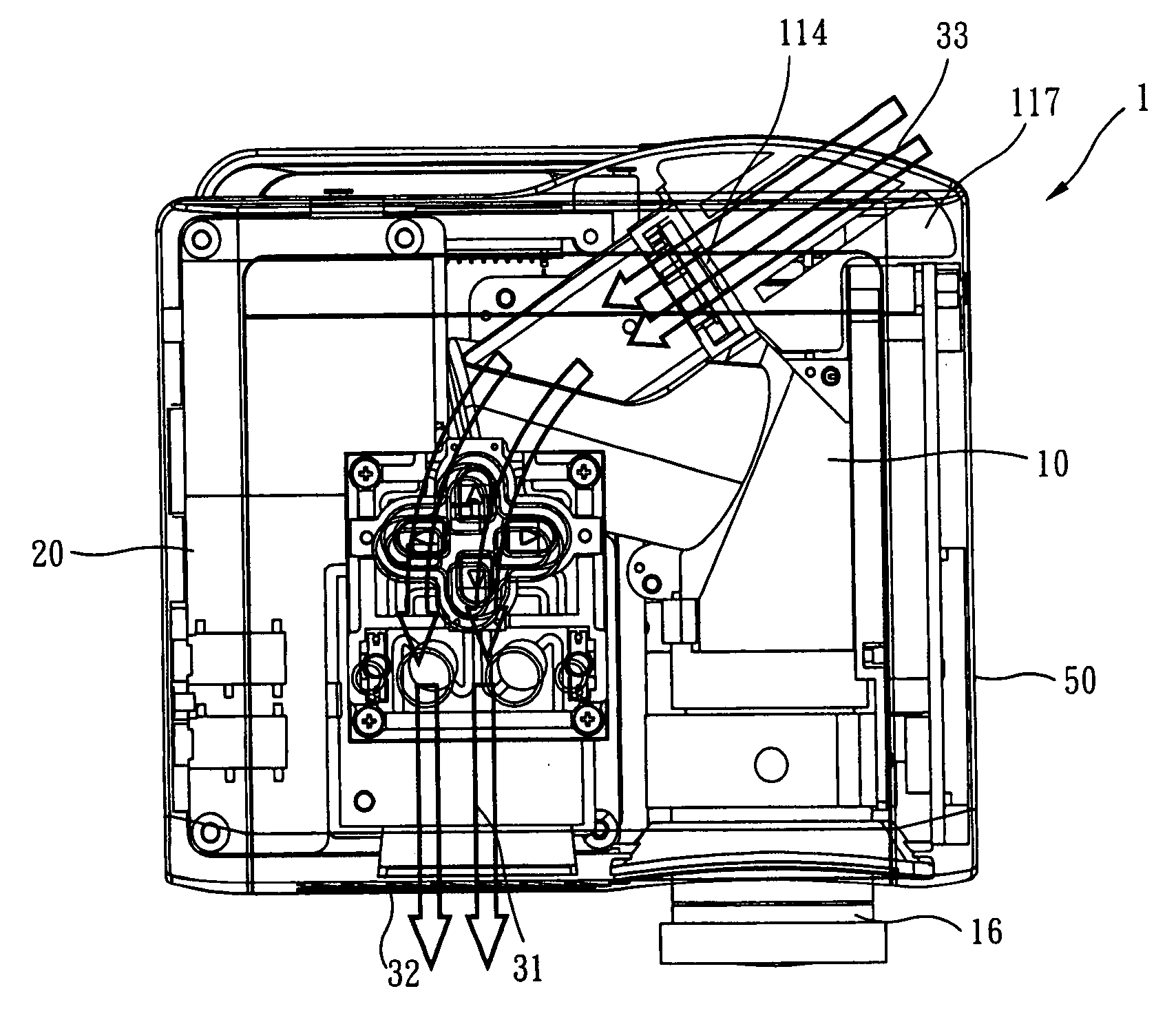
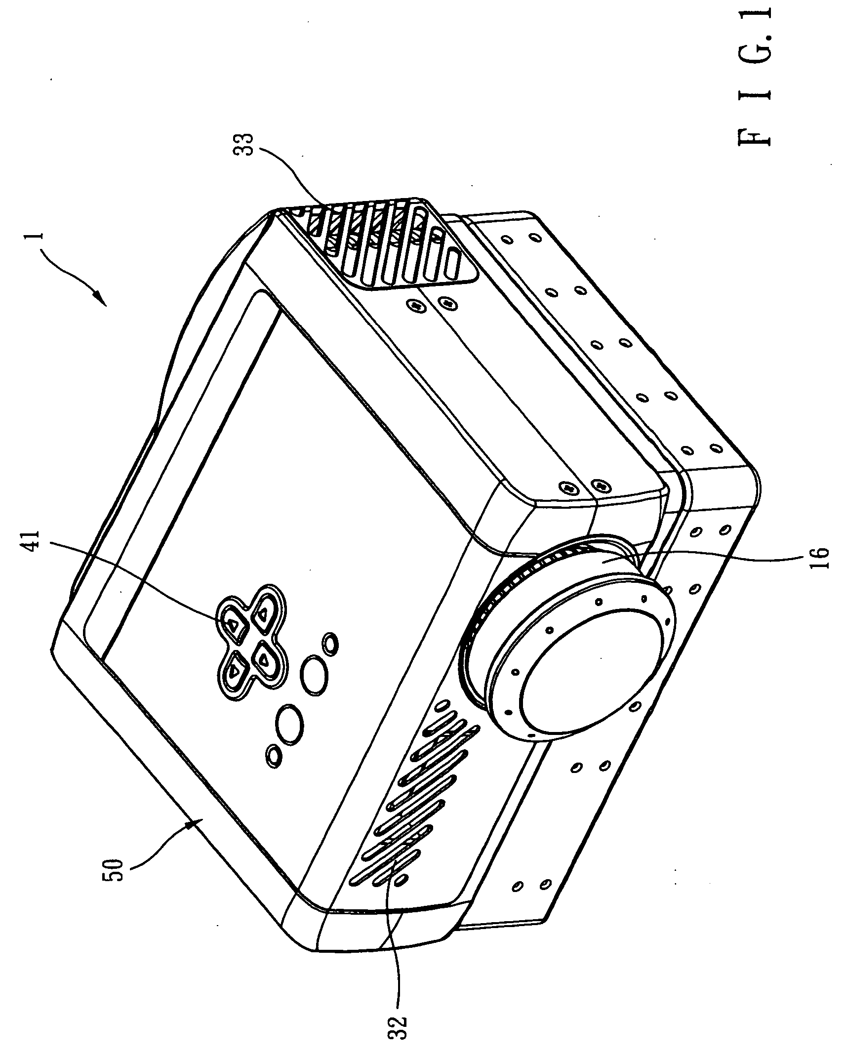
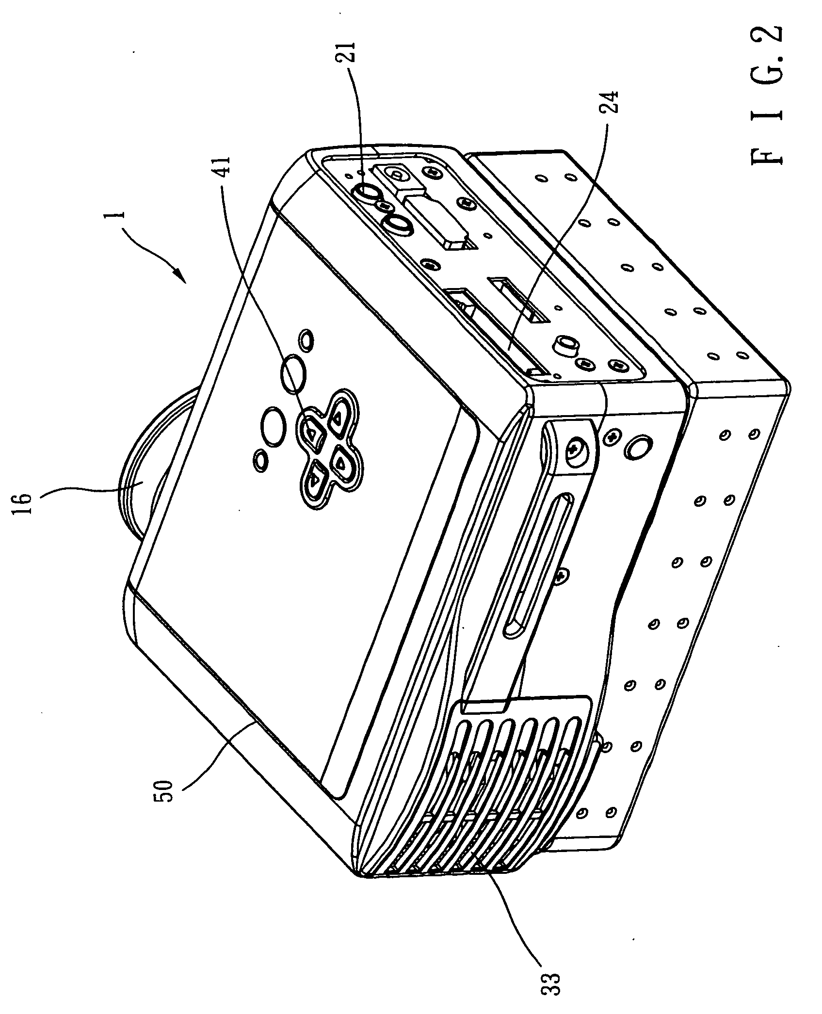
[0020] Please refer to FIG. 1 to FIG. 5. The figures describe a preferred embodiment of the image projector that utilizes a light emitting diode (LED) as its illuminator according to the present invention. FIG. 1 illustrates the frontal stereoscopic view of the exterior appearance of the image projector that utilizes a light emitting diode as illuminator. FIG. 2 illustrates the posterior stereoscopic view of the exterior appearance of the image projector as shown in FIG. 1. FIG. 3 illustrates a perspective view of such image projector as in FIG. 1 from a different angle. FIG. 4 illustrates a composite drawing of the internal optical engine, PCB module and the lower frame of the main frame of the image projector as shown in FIG. 1. FIG. 5 illustrates the composite drawing of the heat sink module, operation interface module and the upper frame of the main frame of the image projector as shown in FIG. 1.

[0021] As shown in FIGS. 3, 4 and 5, the image projector 1 of this invention that ...


PUM


Abstract

An image projector having a LED light source comprises: an optical engine using the LED as the light source, a PCB module, a heat sink module and a main frame. The printed circuit board (PCB) module further comprises: a first circuit board, a second circuit board, at least one I / O interface for connecting an external device, at least one card reader for connecting an external memory card, and a control unit for processing the image data received from the I / O interface or card reader and projecting the image by using the optical engine. The first circuit board and second circuit board are furnished in an overlap and parallel manner to decrease the space consumption. The heat sink module comprises a fan, an air inlet and an air outlet, which substantially forms a heat dissipating passage from the air inlet through the fan toward the air outlet. The LED and control unit are located in the heat dissipating passage for increasing better heat dissipation effect.

Description

BACKGROUND OF INVENTION [0001] 1. Field of the Invention [0002] This invention is related to an image projector; in particular, is related to an image projector having a LED as the light source. [0003] 2. Description of the Prior Art [0004] The conventional image projector has reached the threshold in effectively sizing down due to the limitation in the design of the optical engine, the PCB module and the heat-dissipating route. On one hand, the complexity of the optical elements and the design of the light path prevented smaller space usage in designing the image projector; on the other hand, the complexity and the numerous electronic elements used prevented the minimization of the printed circuit board (PCB). Moreover, the large quantity of heat generated by the illuminator of the optical engine and the microprocessor of the PCB module has to be effectively dissipated by using two or more units of bigger-size high power fan combined with a wide, smooth heat-dissipating route in th...

Claims


Application Information

Patent Timeline
Patent Type & Authority Applications(United States)
IPC IPC(8): G03B21/16G03B21/00G03B21/12
CPCG03B21/12G03B21/16H04N9/3144H04N9/3197
Inventor WU, CHAO HSIEN
Owner HON HAI PRECISION IND CO LTD
Why Eureka
Try Eureka