Multifunctional rear view mirror mounted device for bicycles which provides display information

a rear view mirror and information technology, applied in the field of vehicles, can solve the problems of unsuitable rear-view mirrors to improve use safety and comfort in modern transportation means, and the risk of serious accidents of cyclists is very serious, so as to improve the operation of other conventional on-board user devices, preserve the vehicle user performance unaltered, and avoid the effect of hindering and distracting users

Active Publication Date: 2012-02-21
SELLE ITALA
View PDF2 Cites 15 Cited by
  • Summary
  • Abstract
  • Description
  • Claims
  • Application Information

AI Technical Summary

Benefits of technology

[0011]Within the scope of the above mentioned aim, a main object of the invention is to provide such a rear-view mirror which comprises specifically designed built-in functional components, allowing it to also operate as a smart information store and dispenser for storing and delivering information useful for driving a bicycle, or transport means, while preserving the vehicle user performance unaltered, and without hindering and distracting the user.
[0012]Another object of the present invention is to provide such a rear-view mirror which can be advantageously used also in cars, motorcycles and so on, so as to provide an auxiliary device for improving the operation of other conventional on-board user devices.
[0013]Yet another object of the invention is to provide such a rear-view mirror which, owing to its specifically designed constructional features, is very reliable and safe in operation.
[0014]Yet another object of the present invention is to provide such a rear-view mirror construction, which can be easily made starting from easily available elements and materials and which, moreover, is very competitive from a mere economic standpoint.

Problems solved by technology

On the contrary, notwithstanding the above, a cyclist operates in an operating condition subjected to possible impacts from other transport means or vehicles, with consequent possible serious dangers, since said other vehicles are usually driven on the same road with a speed and pushiness much greater than that of a bicycle.
Thus, even a slight accident to a cyclist would be very serious because of the above lacking of any physical protection on the bicycle.
However, at present, prior rear-view mirrors are unsuitable to improve use safety and comfort in modern transport means and, in particular, in a bicycle.

Method used


Image

  • Multifunctional rear view mirror mounted device for bicycles which provides display information
  • Multifunctional rear view mirror mounted device for bicycles which provides display information
  • Multifunctional rear view mirror mounted device for bicycles which provides display information

Examples


Embodiment Construction

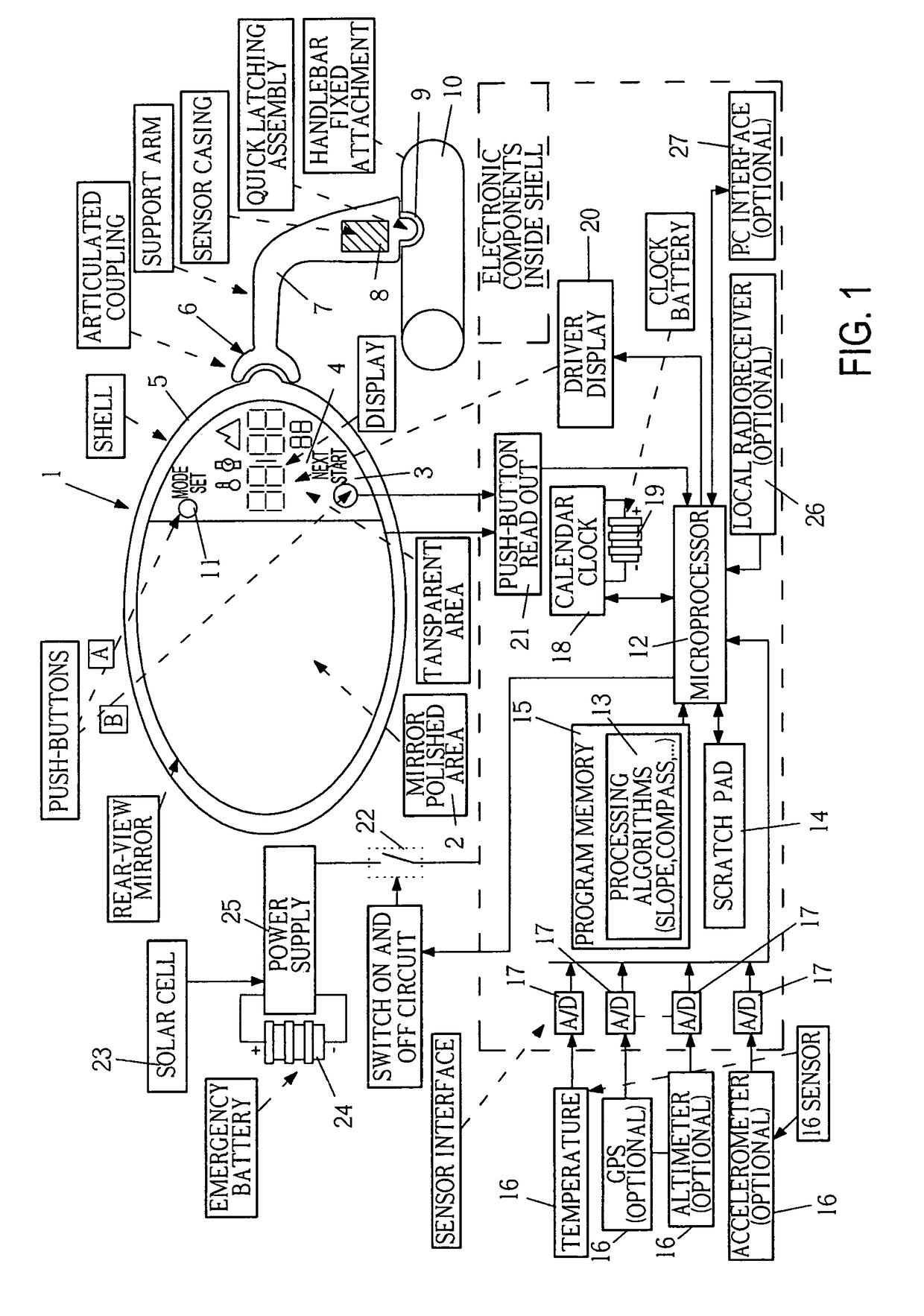
[0021]With reference to the number references of the block diagram shown in FIG. 1, the main element of the inventive device is a smart rear-view mirror 1, said rear-view mirror having a polished mirror surface defining two mirror surface parts, the first of which, that is the mirror area proper 2, has reflecting properties, like a conventional mirror, whereas the second part, that is the area 3, is clear or transpired like a conventional glass material.

[0022]More specifically, the mirror area 2 provides a rear-view mirror function proper, the transparent area 3 having such a size as to not hinder the operation of the part 2, and allowing to also see elements arranged on the rear of the glass surface.

[0023]More specifically, a display assembly 4 is so designed as to properly display different numerical parameters which will be disclosed in a more detailed manner hereinafter.

[0024]The mirror 1 is engaged in a dedicated mirror shell 5, which operates for clamping and supporting the mi...


PUM


Abstract

A multifunctional safety, information and comfort device to be mounted on a vehicle, preferably a bicycle, comprises a rear-view mirror, an alphanumeric and iconographic display, sensors for measuring kinetic and environmental parameters, electronic components for measuring time and controlling said device, and an independent power supply.

Description

BACKGROUND OF THE INVENTION[0001]The present invention relates to a multifunctional device for vehicles.[0002]It is well known that rear-view mirrors represent very useful devices allowing visibility of vehicle traffic on the rear of a road user and, for vehicles, such as cars and motorcycles, the use of rear-view mirrors is absolutely indispensable.[0003]For example, cars conventionally comprise at least three rear-view mirrors, that is a central and two side rear-view mirrors, which must be compulsory installed for meeting law requirements.[0004]Likewise, in a motorcycle it is necessary, for meeting the same law requirements, to mount two rear-view mirrors on the side of the motorcycle handlebar.[0005]On the other hand, is not compulsory to mount rear-view mirrors on bicycles, since a bicycle is considered a low speed vehicle affording the bicycle user comparatively high movement freedom degrees, and an easy visibility even at the user back.[0006]On the contrary, notwithstanding t...

Claims


Application Information

Patent Timeline
Patent Type & Authority Patents(United States)
IPC IPC(8): H01L27/00
CPCA42B3/0426B60R1/12B60R2001/1215B60R2001/1223B60R2001/123B60R2001/1246B60R2001/1253B60R2001/1284B62J29/00B62J45/20B62J45/412B62J45/414B62J50/22
Inventor BIGOLIN, RICCARDO
Owner SELLE ITALA
Why Eureka
Try Eureka