Heat dissipation device

a heat dissipation device and heat dissipation device technology, which is applied in semiconductor devices, lighting and heating apparatus, cooling/ventilation/heating modifications, etc., can solve the problems of troublesome and costly, complex operation of assembly of heat dissipation devices, and large heat generated by electronic components such as central processing units

Inactive Publication Date: 2012-02-21
FU ZHUN PRECISION IND SHENZHEN +1
View PDF13 Cites 11 Cited by
  • Summary
  • Abstract
  • Description
  • Claims
  • Application Information

AI Technical Summary

Benefits of technology

[0006]However, the heat dissipation device usually further includes a fan mounted on the heat sink and a plurality of screws fixing the fan on the heat sink. This makes the operation of assembly of the heat dissipation device more complex, troublesome and costly.

Problems solved by technology

It is well known that, during operation of a computer, electronic components such as central processing units (CPUs) frequently generate large amounts of heat.
This makes the operation of assembly of the heat dissipation device more complex, troublesome and costly.

Method used


Image

  • Heat dissipation device
  • Heat dissipation device
  • Heat dissipation device

Examples


Embodiment Construction

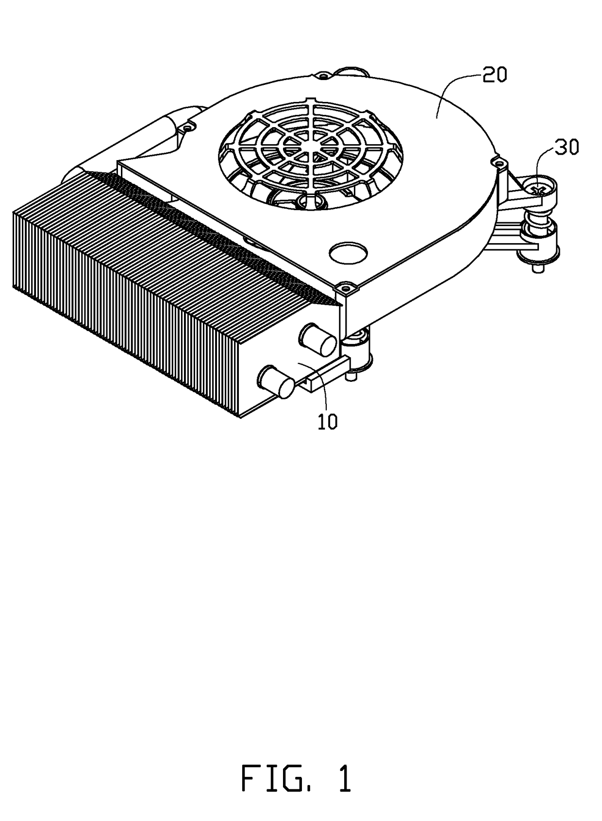
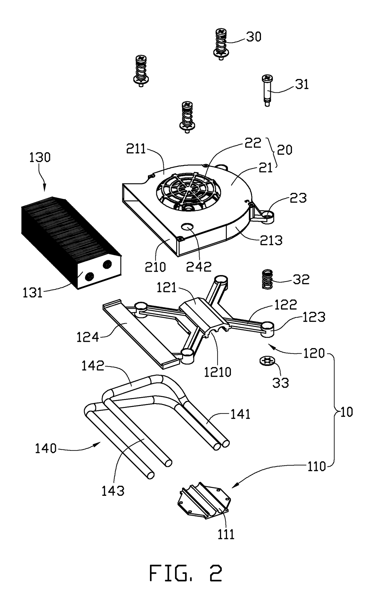
[0015]Referring to FIGS. 1 and 2, a heat dissipation device in accordance with an embodiment of the disclosure is used for dissipating heat generated by an electronic component (not shown) mounted on a printed circuit board 100 (see FIG. 6). The heat dissipation device comprises a heat sink 10, a fan 20, and a plurality of fixing members 30 fixing the fan 20 to the heat sink 10. In the embodiment of the present disclosure, there are four fixing members 30.

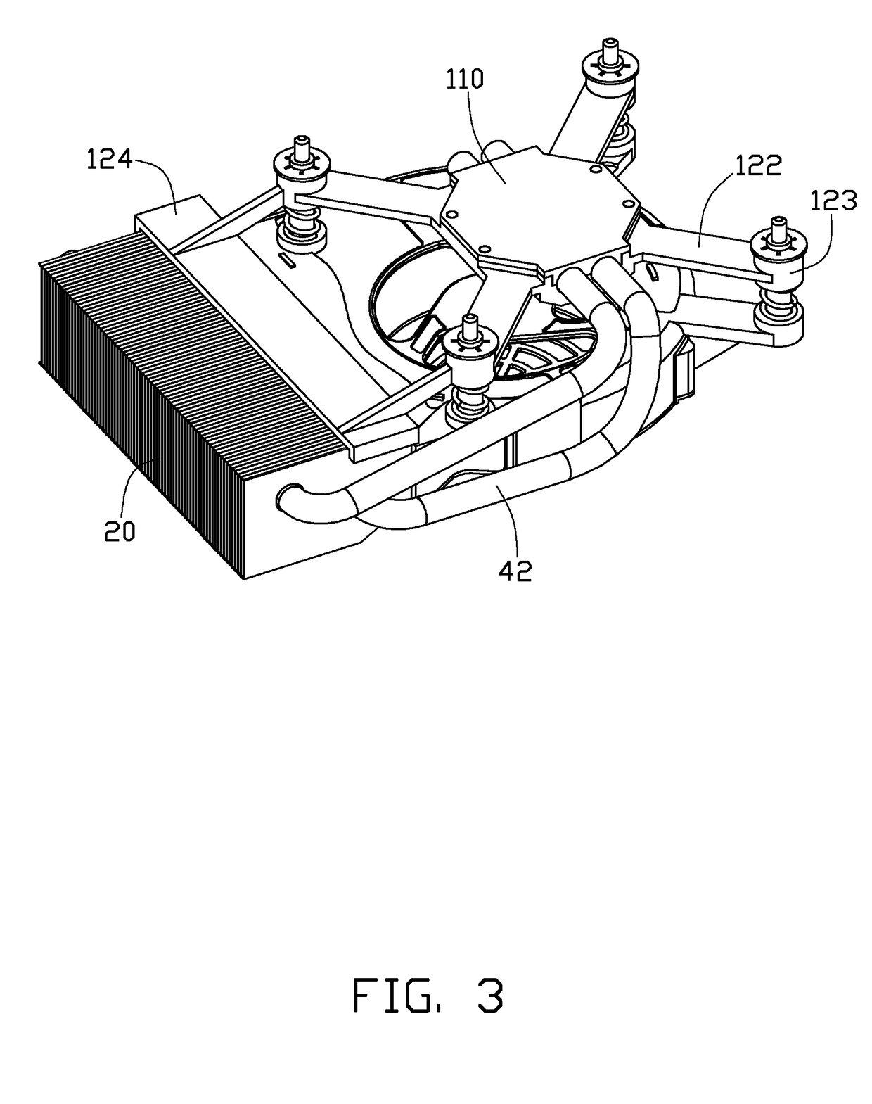
[0016]Referring to FIGS. 3 and 4 also, the heat sink 10 comprises a base 110, a supporting board 120 engaged with the base 110, a fin set 130 disposed on the supporting board 120, and a plurality of heat pipes 140 thermally connecting the base 110, the supporting board 120 and the fin set 130. In the embodiment of the present disclosure, there are two heat pipes 140. Each of the heat pipes 140 comprises an evaporation section 141, a condensation section 143, and a connecting section 142 interconnecting the evaporation section 141 a...


PUM


Abstract

An exemplary heat dissipation device includes a fan having a plurality of first fixing cylinders, a heat sink having a plurality of second fixing cylinders, and a plurality of fasteners fixing the fan to the heat sink. Each of the fasteners includes a screwing post, an elastic member encircling the screwing post, and an annular fastening collar engaging with the screwing post. Each of the fasteners extends through a corresponding first fixing cylinder of the fan and a corresponding second fixing cylinder of the heat sink. The elastic member of each fastener is compressed between the corresponding first fixing cylinder and the corresponding second fixing cylinder.

Description

BACKGROUND[0001]1. Technical Field[0002]The disclosure relates to heat dissipation devices, and, more particularly, to a heat dissipation device for dissipating heat generated by an electronic component.[0003]2. Description of Related Art[0004]It is well known that, during operation of a computer, electronic components such as central processing units (CPUs) frequently generate large amounts of heat. The heat must be quickly removed from the electronic component to prevent it from becoming unstable or being damaged. In many or most computers, a heat dissipation device is utilized to dissipate the heat from the electronic component.[0005]A typical heat dissipation device includes a heat sink, and a plurality of fasteners for keeping the heat sink in contact with the electronic component. The heat sink includes a base and a fin unit arranged on the base. The base includes a rectangular body, and four ears extending outwards from four corners of the body. Each of the fasteners includes...

Claims


Application Information

Patent Timeline
Patent Type & Authority Patents(United States)
IPC IPC(8): H05K7/20F28D15/00H01L23/34F28F7/00
CPCH01L23/4006H01L23/427H01L23/467H01L2023/4081H01L2924/0002H01L2924/00
Inventor LIU, JIAN
Owner FU ZHUN PRECISION IND SHENZHEN
Why Eureka
Try Eureka