Image forming apparatus

a technology of forming apparatus and forming tube, which is applied in the direction of digital output to print units, instruments, electrographic processes, etc., can solve the problems that the techniques described in documents 1 and 2 cannot be directly adopted, and the idea described above cannot be realized, so as to improve the appeal of users and increase the cost of the apparatus

Active Publication Date: 2012-03-20
SHARP KK
View PDF33 Cites 2 Cited by
  • Summary
  • Abstract
  • Description
  • Claims
  • Application Information

AI Technical Summary

Benefits of technology

[0009]In designing an image forming apparatus, a problem to be solved is to provide updated display of communication history that may change in a sleep mode when power supply to the apparatus is shut-off, so as to enable the user to grasp the state of communication in the sleep mode.
[0033]According to the present invention, it is possible to update and display communication history that may change in the sleep mode and, therefore, it is possible to let the user understand the state of communication in the sleep mode.

Problems solved by technology

Though it is possible by the techniques described in Documents 1 and 2 to transmit necessary information to the user or service person even when power is off by displaying information before power off on the electronic paper, the idea described above cannot be realized.
Specifically, in order to solve such a problem, the techniques described in Documents 1 and 2 cannot directly be adopted.

Method used


Image

  • Image forming apparatus
  • Image forming apparatus
  • Image forming apparatus

Examples


Embodiment Construction

[0046]In the following, an embodiment of the present invention will be described in detail with reference to the appended figures.

[0047]20>

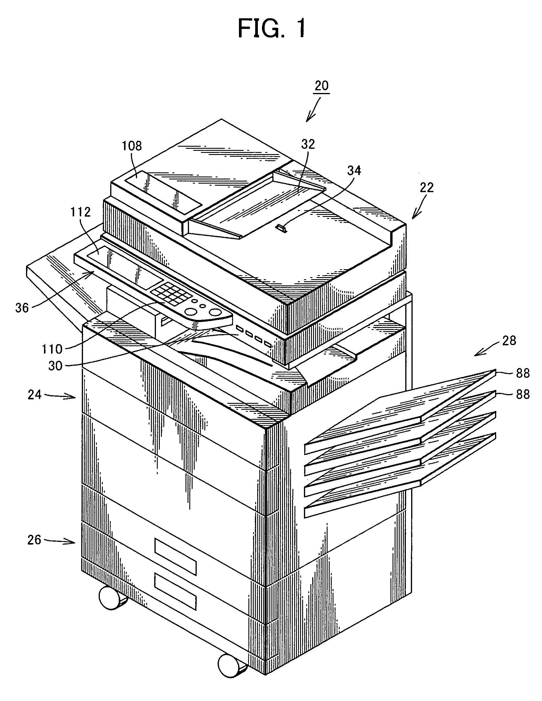
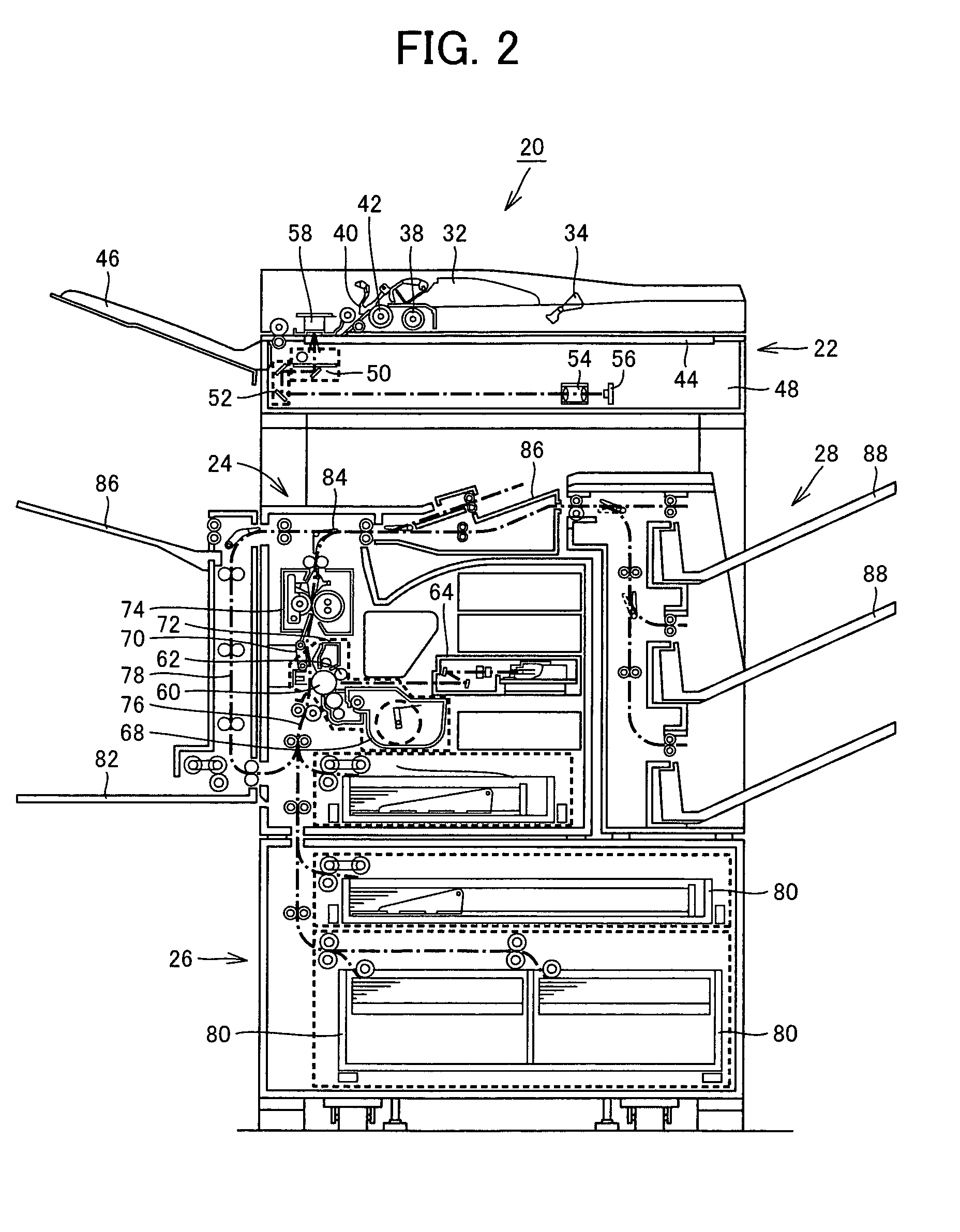
[0048]FIG. 1 is a perspective view showing an appearance of an image forming apparatus 20 in accordance with the embodiment of the present invention, and FIG. 2 schematically shows an internal configuration of image forming apparatus 20.

[0049]Referring to FIGS. 1 and 2, an image forming apparatus 20 in accordance with the present embodiment is a digital multifunctional printer, and it is capable of operating selectively in, for example, a copy mode in which an image of a document is read and printed on a sheet of printing paper, a facsimile mode in which an image of a document is read and transmitted and an image of a document is received and printed on a sheet of printing paper, and a printer mode in which an image received through a network from an information terminal, not shown, is printed on a sheet of printing paper.

[0050]Image forming appa...


PUM


Abstract

An image forming apparatus is provided, in which communication history that may change in a sleep mode is updated and displayed, whereby state of data communication in the sleep mode can be grasped. Even if the image forming apparatus as a whole is stopped, power is supplied only to a communication unit. When data is transmitted / received from an external device, a communication controller of the communication unit that transmitted / received data temporarily drives an electronic paper, so that transmission / reception log is displayed on electronic paper. Thereafter, power supply to the electronic paper is stopped.

Description

CROSS-REFERENCE TO RELATED APPLICATION[0001]This nonprovisional application claims priority under 35 U.S.C. §119(a) on Patent Application No. 2008-058011 filed in Japan on Mar. 7, 2008, the entire contents of which are hereby incorporated by reference.BACKGROUND OF THE INVENTION[0002]1. Field of the Invention[0003]The present invention relates to an image forming apparatus such as a multifunctional printer, having a function of communicating with an external device.[0004]2. Description of the Background Art[0005]Electronic paper is a thin display technology similar to a liquid crystal display and the like, and it has similar appearance as ordinary paper. The electronic paper is characterized in that displayed contents are electrically rewritable, and that power consumption thereof is very low as electric power is unnecessary to retain the displayed contents. In addition, electronic paper is non-volatile, that is, once the displayed contents are rewritten, the displayed contents are ...

Claims


Application Information

Patent Timeline
Patent Type & Authority Patents(United States)
IPC IPC(8): G06F3/12
CPCH04N1/00885H04N1/00896H04N1/00904G03G15/502H04N2201/0094H04N2201/3202
Inventor MIYAKE, KOUJIFUJII, SHUHJIIDO, KAZUHIKOYOSHIMOTO, TSUTOMU
Owner SHARP KK
Why Eureka
Try Eureka