Support structure

a support structure and surface structure technology, applied in the direction of shock absorption devices, elastic dampers, roofs, etc., can solve the problems of difficult high precision achievement, achieve stable softness, reduce impact force, and maintain softness

Inactive Publication Date: 2012-04-17
NISSAN MOTOR CO LTD
View PDF7 Cites 17 Cited by
  • Summary
  • Abstract
  • Description
  • Claims
  • Application Information

AI Technical Summary

Benefits of technology

[0007]A contact surface (such as a surface structure or skin) of an article, according to one or more embodiments of the present disclosure, may include a first projection section inclined in a first direction and may be located separate from a second projection section inclined in a second direction. The two projection sections may be inclined so that a direction of inclination of the two projections intersects. Upon the contact surface being pressed, the respective projection sections deform (or collapse) to approach each other and may come into contact with each other, thereby restricting complete collapse of the projections, and thereby maintaining a soft feeling and decreasing an impact force.
[0008]According to one or more embodiments of the present disclosure, the first projection section and the second projection section may deform and may come into contact with each other so as to restrict complete collapse of the projections, thereby providing a softness feeling. As a result, the softness feeling may be stably obtained regardless of assembly accuracy among parts. Accordingly, no rib-projection combination and / or alignment, requiring precise installation, may be required.

Problems solved by technology

To achieve this a precise locational relationship is required for assembling the tip position of the rib and the projection so that a desired soft feeling may be obtained, which may be difficult to achieve with a high precision.

Method used


Image

  • Support structure
  • Support structure
  • Support structure

Examples


first embodiment

[0023]Hereinafter, the present disclosure will be discussed with reference to the drawings.

[0024]A configuration of a support structure 100 in the first embodiment will be discussed.

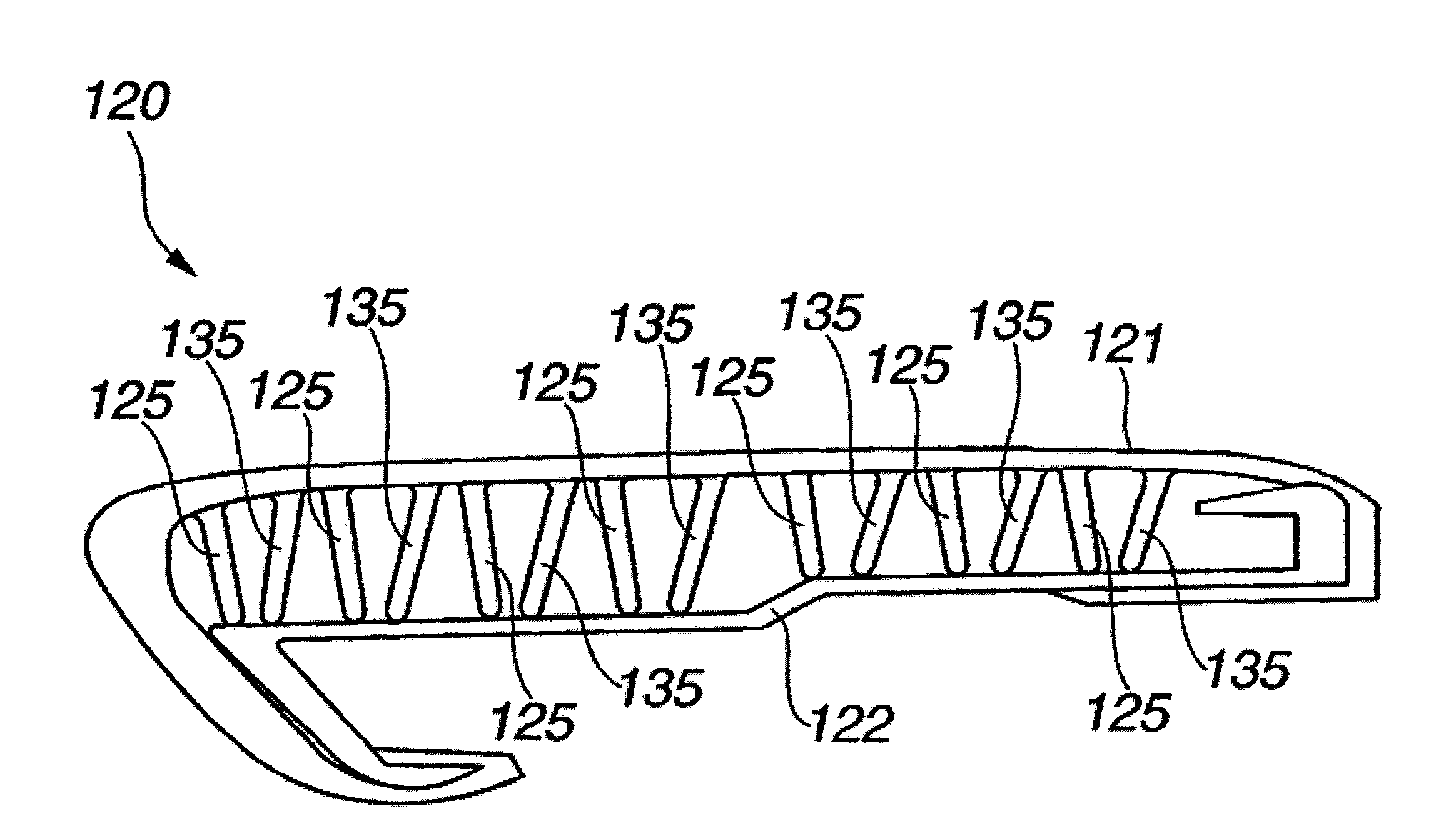
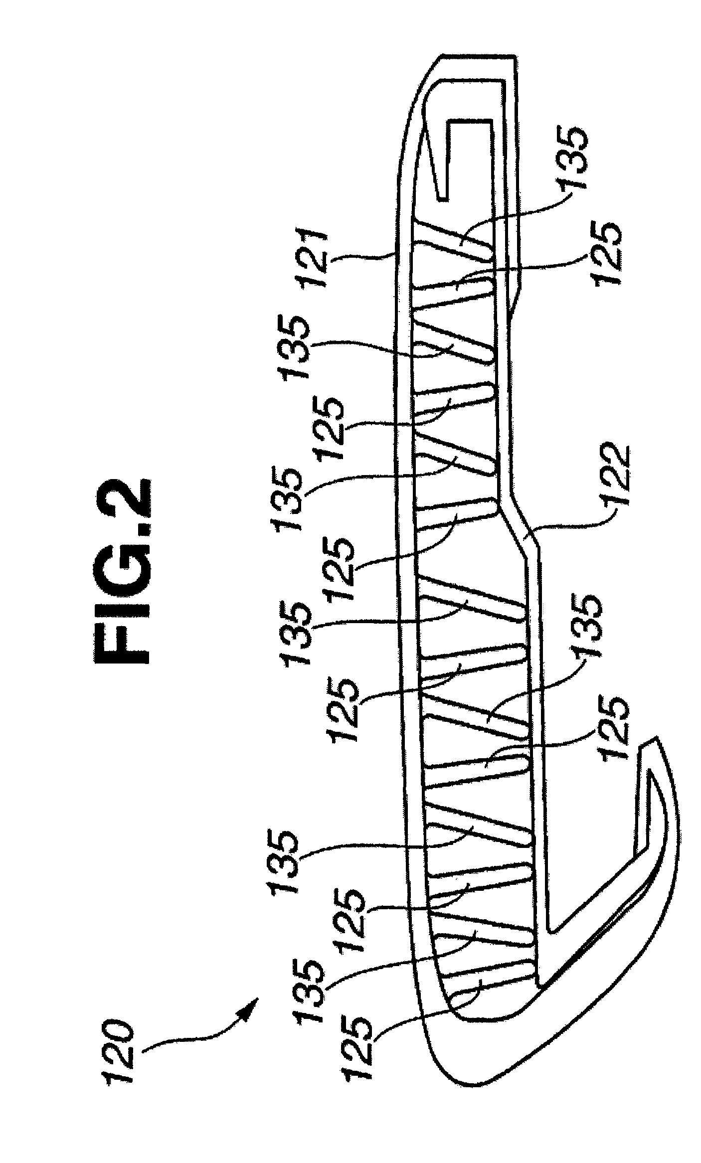
[0025]A support structure 100 in a first embodiment may include a contact surface 120, and a set of ribs 125 serving as first projection sections and a set of ribs 135 serving as second projection sections, which may be disposed on a backside (or underside) of contact surface 120, as shown in FIGS. 1 and 2.

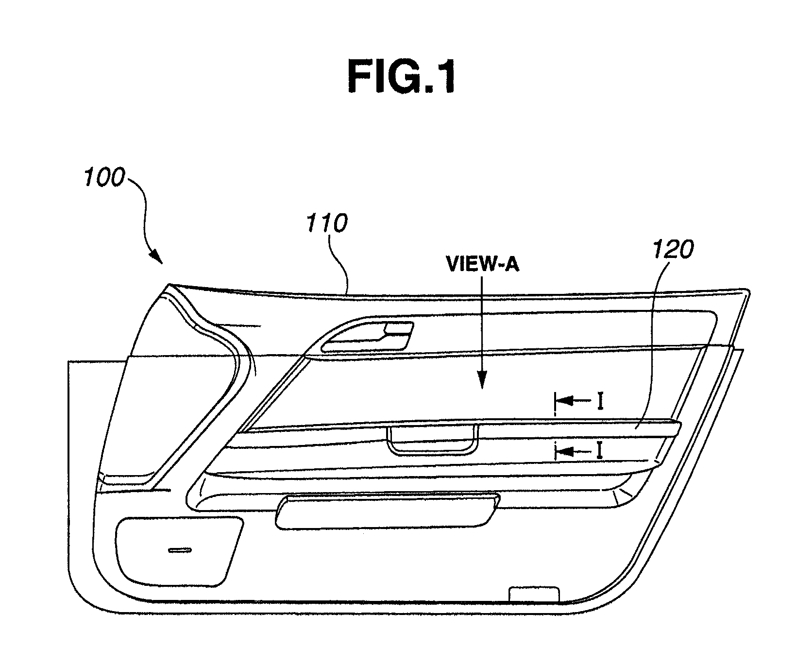
[0026]Referring to FIGS. 1-3, contact surface 120 may be fixed to a door trim 110 and may be assembled to a door panel (not shown) as a single body with door trim 110. Contact surface 120 may include a skin section 121 (which may be a surface of contact) and a base section 122. Ribs 125 and ribs 135 may be formed as projections extending from the backside surface of skin section 121 toward base section 122 and may be located between skin section 121 and base section 122. Ribs 125 and 135 may be regular...

second embodiment

[0040]Hereafter, the present disclosure will be discussed with reference to FIGS. 8-11.

[0041]An arrangement of a support structure 200, according to one or more embodiments of the present disclosure will be discussed.

[0042]Discussion of support structure 200, in the second embodiment will be made only for parts different from those of the first embodiment, omitting discussion for parts similar to those of the first embodiment.

[0043]Support structure 200 for a vehicle may include a contact surface 220, and a plurality of ribs 225 and ribs 235 disposed on an underside of contact surface 220.

[0044]As shown in FIGS. 8-10, contact surface 220 may have ribs 225 and ribs 235 formed as projections extending from a backside surface of a skin section 221 toward a base section 222 and may be regularly located and / or spaced adjacent to each other in such a manner as not to contact with each other, as shown in FIGS. 8-10.

[0045]Referring to FIG. 9 (a cross-sectional view of FIG. 8 along the line ...


PUM

PropertyMeasurementUnit
forceaaaaaaaaaa
inclination angle θ1aaaaaaaaaa

Abstract

In one or more embodiments of the present disclosure a support structure includes a contact surface configured to deform, a base section configured to receive the contact surface, a first set of ribs extending from the contact surface toward the base section and inclined in a first direction, and a second set of ribs extending from the contact surface toward the base section and inclined in a second direction, in which the first set of ribs and the second set of ribs are disposed such that there is no contact with each other in a relaxed position, and in which the first set of ribs and the second set of ribs are configured to deform and contact each other upon application of a force to the contact surface.

Description

CROSS-REFERENCE TO RELATED APPLICATIONS[0001]The present application claims priority from Japanese Patent Application No. 2009-102662, filed Apr. 21, 2009. The contents of the priority application are hereby incorporated by reference in their entirety.BACKGROUND OF INVENTION[0002]1. Field of the Disclosure[0003]This invention relates to a surface structure of an article for providing a low impact or softness feeling to the article.[0004]2. Description of the Related Art[0005]A Japanese patent provisional publication No. 2000-85434 discloses, as a surface structure of an article for providing a softness to the article, a surface in which a rib is formed on the backside of the surface while a projection is formed at a core section for receiving the skin. The rib is formed to be contactable with the projection. When the surface is depressed or pressed upon, the rib of the backside of the surface is brought into contact with the projection so that the rib is elastically deformed, thereb...

Claims


Application Information

Patent Timeline
Patent Type & Authority Patents(United States)
IPC IPC(8): B60N2/46B60N2/75
CPCB60N2/46B60R21/0428Y10T29/49863B32B3/30B32B3/06B32B3/085B32B2307/732B32B2479/00B32B2605/003B32B2607/00B60N2/75B32B7/05
Inventor ISHIKAWA, SHINYA
Owner NISSAN MOTOR CO LTD
Why Eureka
Try Eureka