Controlled retraction syringe and plunger therefor

a syringe and plunger technology, applied in the field of syringes, can solve the problems of blood splattering, high cost to society, repercussions on sufferers, etc., and achieve the effect of not compromising the safety features

Active Publication Date: 2012-05-01
UN HOLDINGS LLC
View PDF25 Cites 27 Cited by
  • Summary
  • Abstract
  • Description
  • Claims
  • Application Information

AI Technical Summary

Benefits of technology

[0009]Preferably, in use the retractable syringe reduces or minimizes blood splattering associated with needle retraction.
[0012]In a first aspect, the invention provides a plunger for a syringe having a retractable needle, said plunger comprising a controlling means which facilitates control of the rate of retraction of said retractable needle when engaged with said plunger.
[0013]In a second aspect, the invention provides a syringe having a barrel, a retractable needle and a plunger engageable with said retractable needle, said plunger comprising a controlling means which facilitates control of the rate of retraction of said retractable needle when engaged with said plunger.
[0014]Suitably, retraction of said retractable needle is facilitated by a biasing means, such as a spring or other compressible and / or de-compressible device.
[0015]Preferably, said spring is initially compressed so that decompression of said spring facilitates retraction of said retractable needle.
[0021]In one particular form, said syringe further comprises a retaining member that facilitates initial retention of said retractable needle at a needle end of said barrel.

Problems solved by technology

The practice of sharing syringes without adequate sterilization between successive users is a major contributor to the transfer of Human Immunodeficiency Virus (HIV) and Hepatitis with subsequent severe repercussions for the sufferer and at a high cost to society for supporting and providing medical attention to sufferers.
However, generally spring decompression is relatively uncontrolled, which in use can lead to excessively forceful needle retraction that can result in blood splattering as air is forced from the syringe barrel as the needle retracts into the barrel.

Method used


Image

  • Controlled retraction syringe and plunger therefor
  • Controlled retraction syringe and plunger therefor
  • Controlled retraction syringe and plunger therefor

Examples


Embodiment Construction

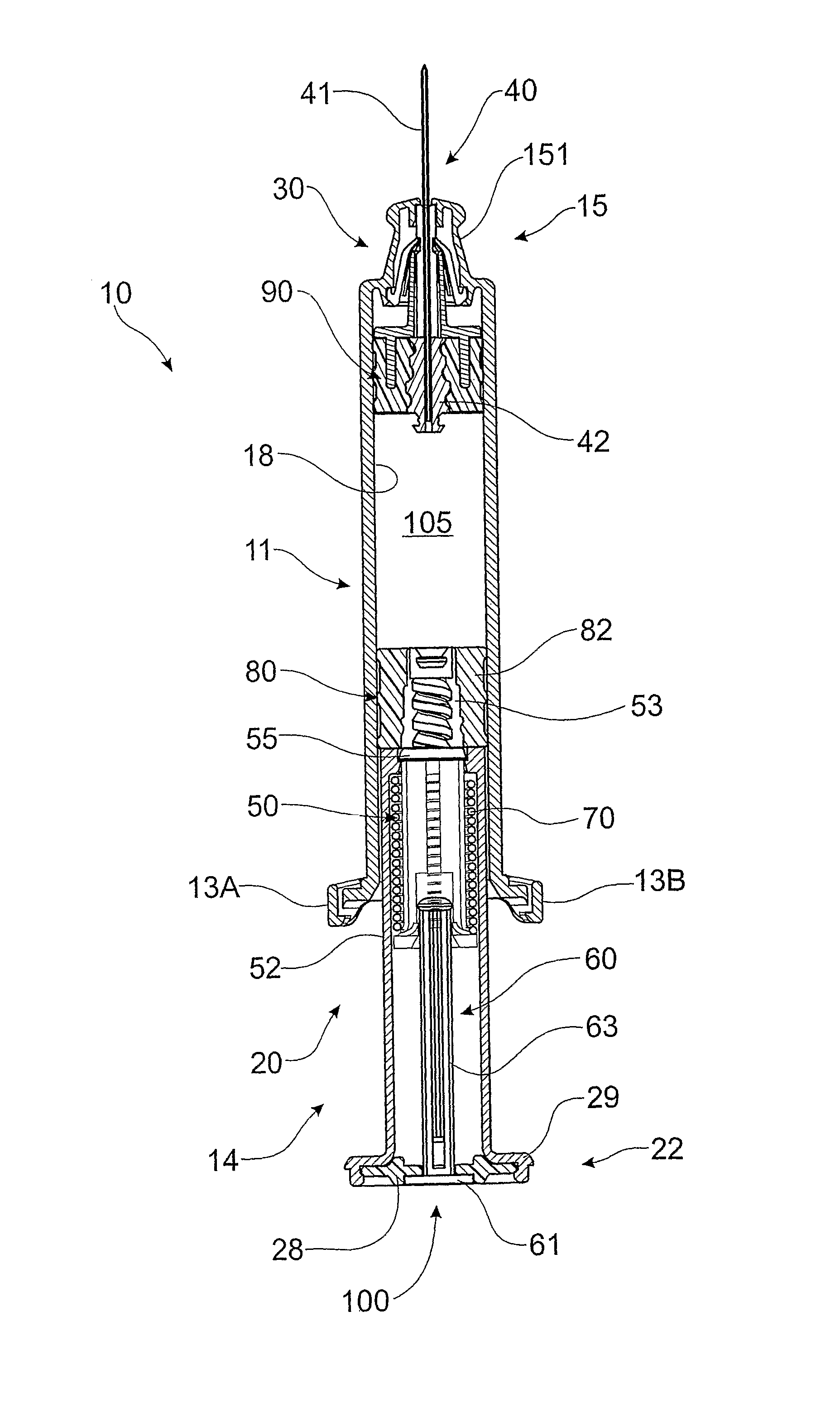
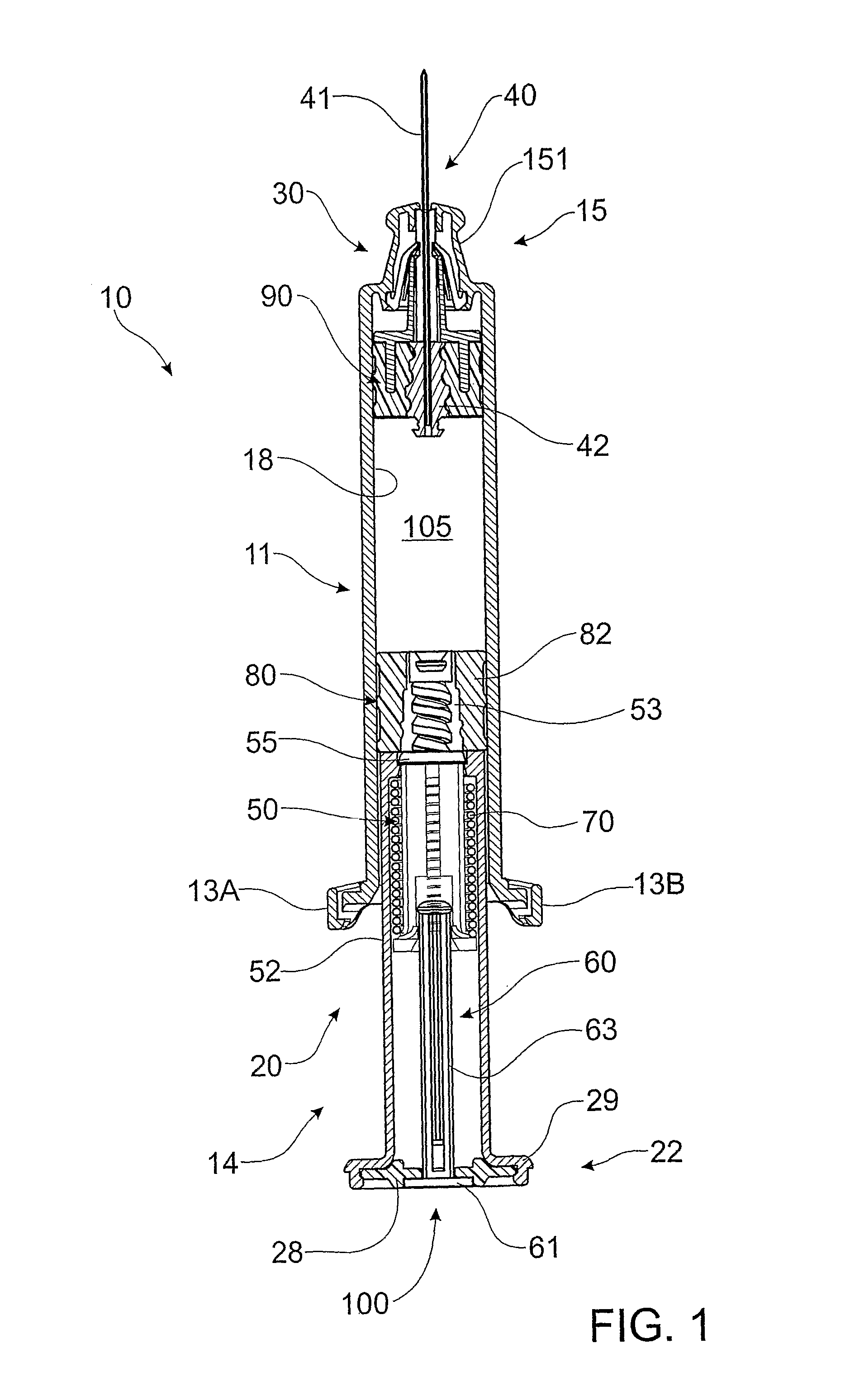
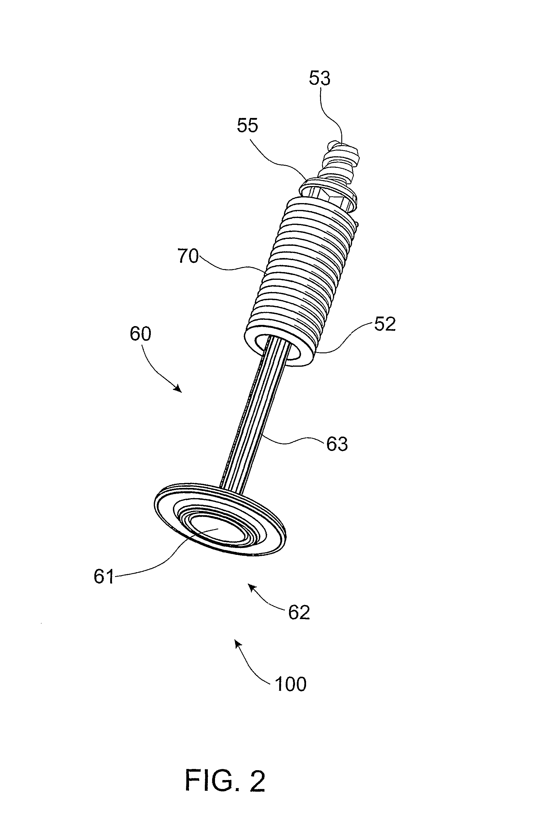
[0052]Referring to FIG. 1 and FIG. 2, an embodiment of syringe 10 comprises barrel 11 and plunger 20 having sealing means 80 mounted to plunger 20. Barrel 11 comprises plunger end 14 at which are located finger grips 13A, 13B, and needle end 15 having domed portion 151 onto which can be mounted a sheath or other protective cover for cannula 41 (not shown). Inside domed portion 151 is mounted retaining member 30, a needle mount in the form of needle seal 90 and retractable needle 40 that comprises cannula 41 and retractable needle body 42. Mounting of retaining member 30 inside needle end 15 of barrel 11 will be described more clearly with reference to FIG. 5.

[0053]Barrel 11 further comprises inside wall 18 which, together with needle seal 90 and plunger seal 80 define fluid space 105 inside barrel 11. In use, plunger 20 is movable axially into fluid space 105 to facilitate delivery of fluid contents of syringe 10. In a preferred embodiment, fluid space 105 is prefilled with the flui...


PUM


Abstract

A retractable syringe (11) and plunger (20) therefore are provided, whereby the plunger comprises a controlling means (62) which facilitates control of the rate of retraction of the retractable needle. By controlling the rate of needle retraction, the likelihood of blood spattering is reduced, thereby improving the user-friendliness and appeal of the retractable syringe. Typically, the syringe is a prefilled syringe. Following plunger depression, a symmetrical ejector member (92) releases the retractable needle (40) from a retaining member (30) to thereby allow retraction of the retractable needle. Needle retraction is facilitated by a biasing means (70), such as a spring or other compressible and / or de-compressible device. The plunger comprises a plunger housing (21), in which is located the controlling means. The controlling means may be a pneumatic air space (324) inside the plunger housing which automatically acts against the retracting needle to thereby control or regulate the rate of retraction.

Description

[0001]This application is a national stage application under 35 U.S.C. §371 of PCT / AU2006 / 000516, filed Apr. 18, 2006, which claims the benefit of Australian Patent Application Nos. 2005901892, filed Apr. 15, 2005; 2005901893, filed Apr. 15, 2005; and 2005906768, filed Dec. 2, 2005, all of which are hereby incorporated by reference in their entirety.FIELD OF THE INVENTION[0002]THIS INVENTION relates to syringes. More particularly, this invention relates to a retractable syringe that includes a needle retraction mechanism to prevent re-use of the syringe, wherein the needle retraction mechanism acts in a controlled manner.BACKGROUND OF THE INVENTION[0003]The practice of sharing syringes without adequate sterilization between successive users is a major contributor to the transfer of Human Immunodeficiency Virus (HIV) and Hepatitis with subsequent severe repercussions for the sufferer and at a high cost to society for supporting and providing medical attention to sufferers.[0004]In re...

Claims


Application Information

Patent Timeline
Patent Type & Authority Patents(United States)
IPC IPC(8): A61M5/00A61M5/32A61M1/00
CPCA61M5/3234A61M5/502A61M5/508A61M2005/3241A61M2005/3235A61M2005/3236A61M2005/3231
Inventor JUDD, DAMIENKAAL, JOSEPH HERMESTHORLEY, CRAIG STEPHEN
Owner UN HOLDINGS LLC
Why Eureka
Try Eureka