Method and apparatus for controlling head flying height in a disk drive

Inactive Publication Date: 2012-05-01
KK TOSHIBA
View PDF26 Cites 4 Cited by
  • Summary
  • Abstract
  • Description
  • Claims
  • Application Information

AI Technical Summary

Problems solved by technology

Consequently, the head will possibly fail, in some cases, to have a flying height optimal to the conditions in which the hard disk is actually used, even if the preset amount of heat is applied to the slider.

Method used


Image

  • Method and apparatus for controlling head flying height in a disk drive
  • Method and apparatus for controlling head flying height in a disk drive
  • Method and apparatus for controlling head flying height in a disk drive

Examples


Embodiment Construction

[0017]Various embodiments will be described hereinafter with reference to the accompanying drawings.

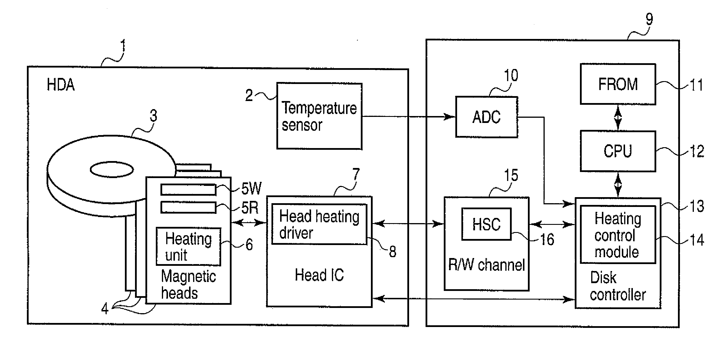
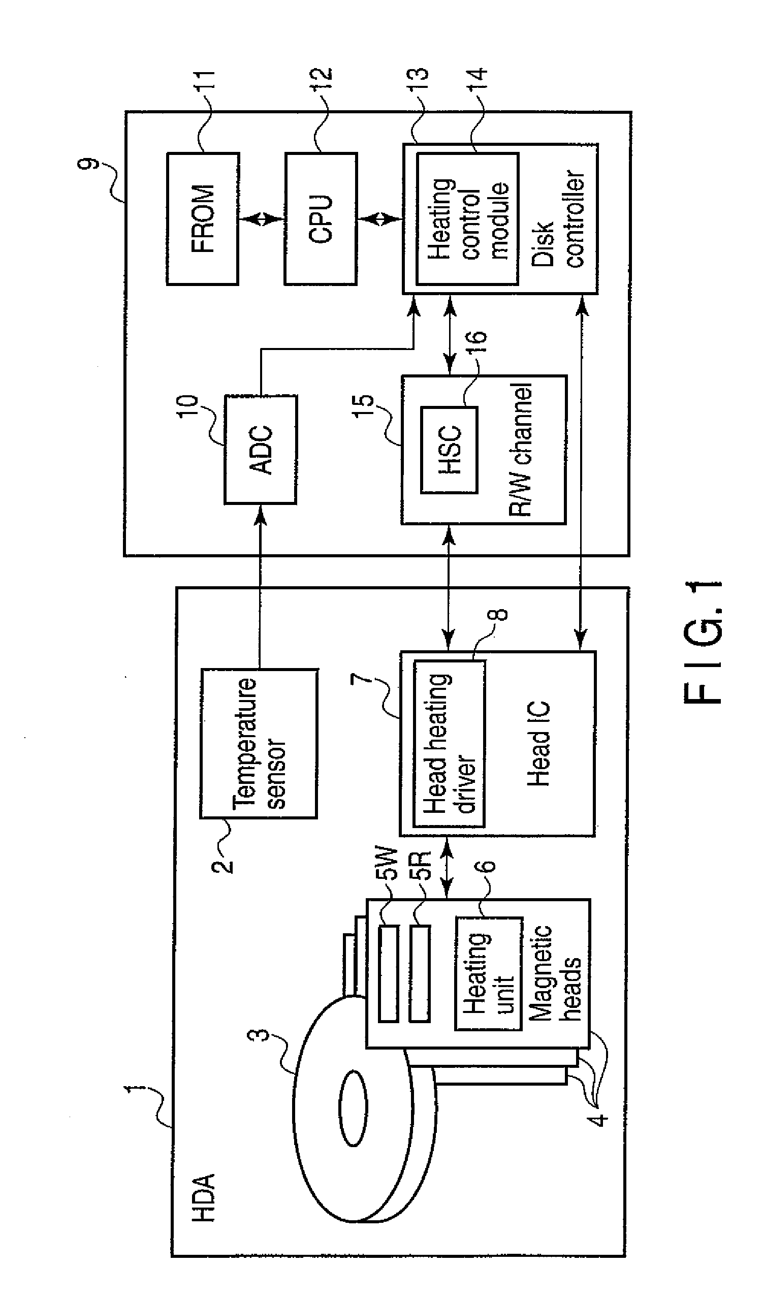
[0018]In general, according to one embodiment, a disk drive includes a measuring module, a flying height controller, a detection module, and a controller. The measuring module is configured to measure the flying height that the head has with respect to the disk. The flying height controller is configured to control the head flying height in accordance with a value preset for the head flying height. The detection module is configured to detect the values representing the environmental elements of the head. The controller is configured to adjust the preset value in accordance with the flying height measured by the measuring module and values detected by the detection module if environmental changes are detected from the environmental element values output from the detection module.

[0019]That is, the disk drive according to the embodiment utilizes harmonic sensing control (hereinafter re...


PUM


Abstract

According to one embodiment, a disk drive includes a measuring module, a flying height controller, a detection module, and a controller. The measuring module is configured to measure the flying height that the head has with respect to the disk. The flying height controller is configured to control the head flying height in accordance with a value preset for the head flying height. The detection module is configured to detect the values representing the environmental elements of the head. The controller is configured to adjust the preset value in accordance with the flying height measured by the measuring module and values detected by the detection module if environmental changes are detected from the environmental element values output from the detection module.

Description

CROSS-REFERENCE TO RELATED APPLICATIONS[0001]This application is based upon and claims the benefit of priority from Japanese Patent Application No. 2010-042518, filed Feb. 26, 2010; the entire contents of which are incorporated herein by reference.FIELD[0002]Embodiments described herein relate generally to a technique of controlling head flying height, for use in disk drives.BACKGROUND[0003]In most disk drives, a representative example of which is the hard disk drive, a head reads or writes data on or from a disk used as a recording medium, while it is flying above the disk. The flying height of the head influences the data recording and reproducing characteristic of the disk drive, and should therefore be set to an optimal value.[0004]In order to set the flying height of the head to an optimal value, a technique may be used which first measures the head flying height and then adjusts the head flying height in accordance with the value measured. A method of adjusting the head flying...

Claims


Application Information

Patent Timeline
IPC IPC(8): G11B5/60
CPCG11B5/6005G11B5/6064
Inventor TSUNODA, MASAHIKOTANAKA, AYA
Owner KK TOSHIBA
Why Eureka
Try Eureka