Speaker system
a speaker system and speaker technology, applied in the field of speaker systems, can solve the problems of difficult to realize a speaker system which is small and capable of reproducing a bass sound, difficult to handle powdery activated carbon, and extremely difficult to stably fill powdery activated carbon into a narrow tube, so as to minimize the flow of moistur
- Summary
- Abstract
- Description
- Claims
- Application Information
AI Technical Summary
Benefits of technology
Problems solved by technology
Method used
Image
Examples
embodiment 1
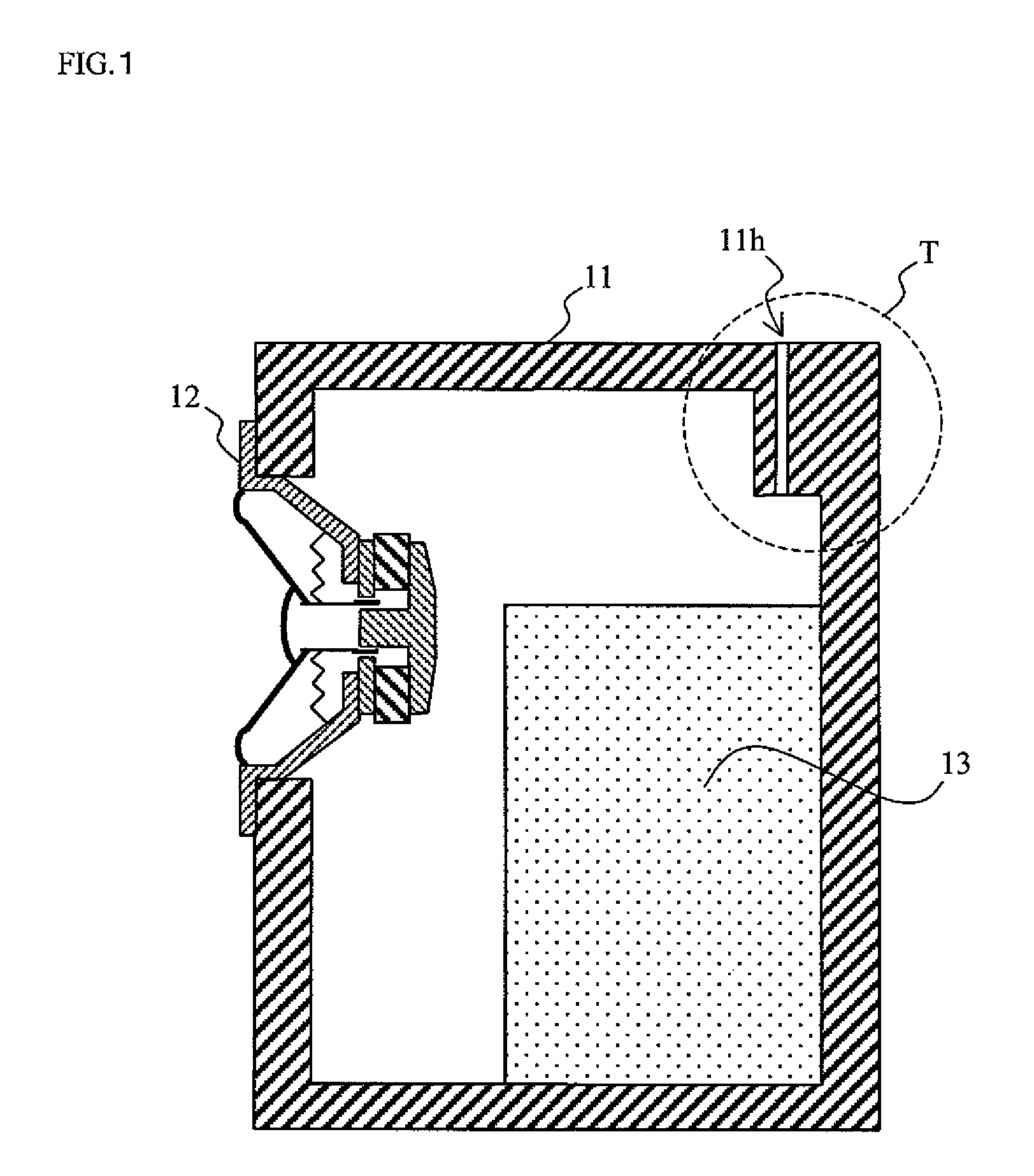
[0064]FIG. 1 is a tectonic profile of a speaker system according to embodiment 1 of the present invention. As shown in FIG. 1, the speaker system is a closed-type speaker system, and includes a cabinet 11, a speaker unit 12 and a gas adsorbent 13.
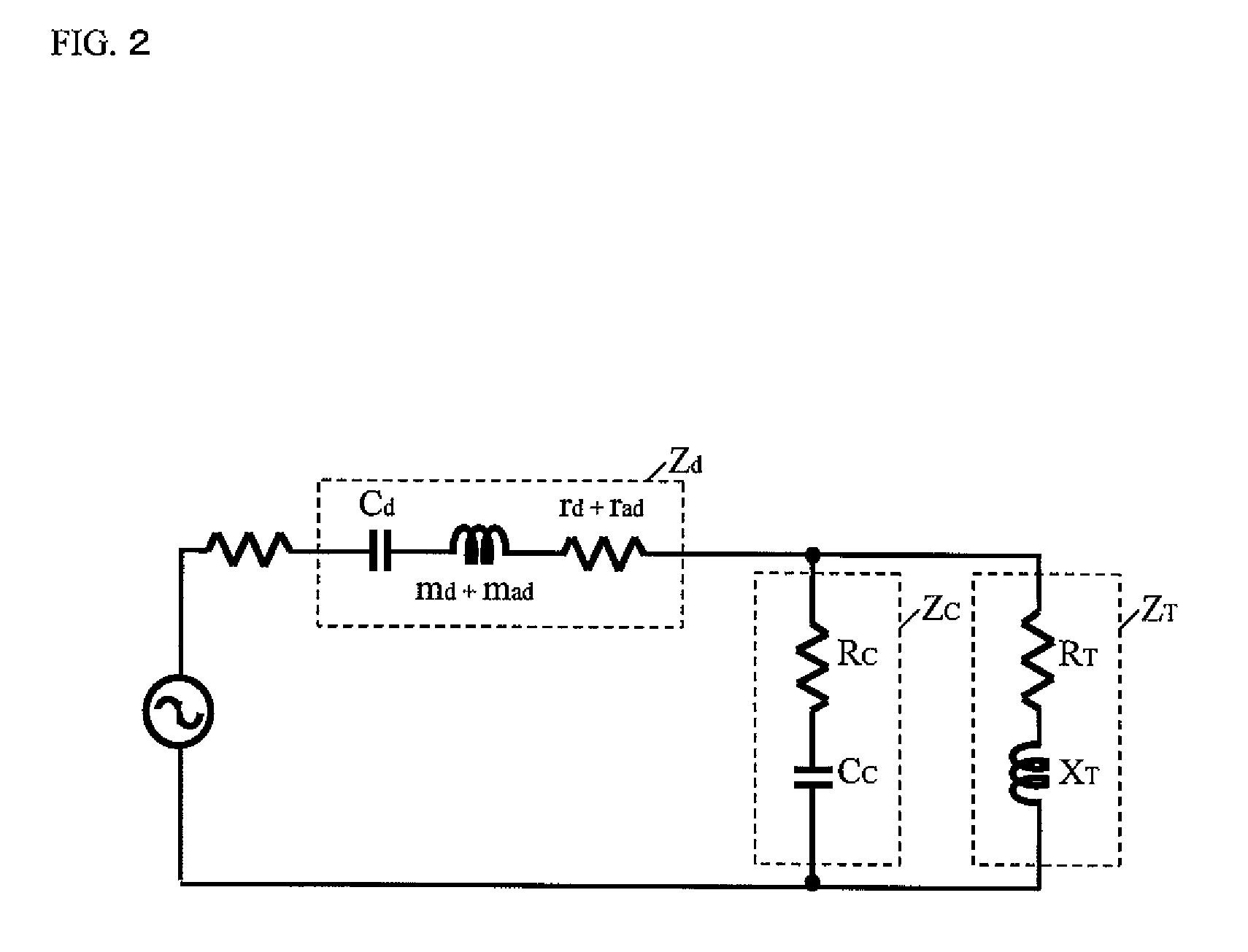
[0065]The speaker unit 12 is fixed to the cabinet 11, and the speaker unit 12 includes a diaphragm and an edge which are each made from a moisture-impermeable material. The cabinet 11 is also made from the moisture-impermeable material. A tubular structure T has a tubular hollow Th which allows ventilation between an inside and an outside of the cabinet 11, and the tubular structure T is configured with the cabinet 11. Specifically, a through-hole 11h is formed on a top surface of the cabinet 11, and the through-hole 11h forms the tubular hollow Th. A length and an effective radius of the tubular hollow Th are set such that a resonant frequency, which is determined in accordance with an acoustic impedance of the tubular structure T and an a...
embodiment 2
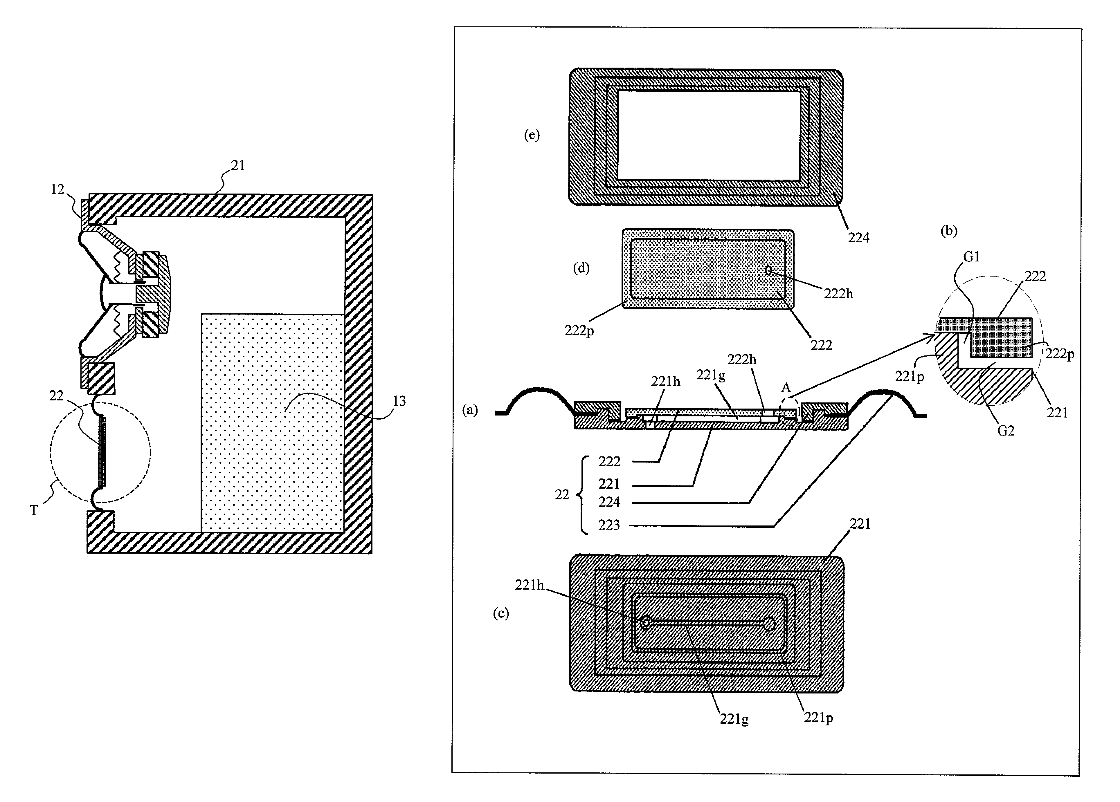
[0094]FIG. 5 is a tectonic profile of a speaker system according to embodiment 2 of the present invention. As shown in FIG. 5, the speaker system is a drone cone type speaker system, and includes a cabinet 21, the speaker unit 12, the gas adsorbent 13, and a drone cone 22. The speaker system according to the present embodiment is different form the speaker system shown in FIG. 1 in that the cabinet 21 is used in replacement of the cabinet 11, and further the drone cone 22 is included. Still further, the tubular structure T is configured with the drone cone 22. Hereinafter, the different points will be mainly described.
[0095]In addition to the speaker unit 12, the drone cone 22 is fixed to the cabinet 21, and the cabinet 21 is made from the moisture-impermeable material.
[0096]The drone cone 22 includes, as shown in FIG. 6, a first diaphragm 221, a second diaphragm 222, an edge 223, and a fixing material 224. These sections are each made from the moisture-impermeable material. FIG. 6 ...
embodiment 3
[0110]FIG. 9 is a tectonic profile of a speaker system according to embodiment 3 of the present invention. In FIG. 9, the speaker system is the closed-type speaker system, and includes a cabinet 31, the speaker unit 12, the gas adsorbent 13 and a screw 32. The speaker system according to the present embodiment is different from the speaker system shown in FIG. 1 in that the cabinet 31 is used in replacement of the cabinet 11, and the screw 32 is further included. Further, the tubular structure T is configured with the cabinet 31 and the screw 32. Hereinafter, the different points will be mainly described.
[0111]The speaker unit 12 is fixed to the cabinet 31, and the cabinet 31 is made from the moisture-impermeable material. As shown in FIG. 10, a through-hole 31h is formed in the cabinet 31, and an inner surface of the through-hole 31h is shaped so as to accommodate screw threads and thread grooves of the screw 32. FIG. 10 is an enlarged view of the tubular structure T shown in FIG. ...
PUM
 Abstract
Description
Claims
Application Information
 - R&D
- Intellectual Property
- Life Sciences
- Materials
- Tech Scout
- Unparalleled Data Quality
- Higher Quality Content
- 60% Fewer Hallucinations
Browse by: Latest US Patents, China's latest patents, Technical Efficacy Thesaurus, Application Domain, Technology Topic, Popular Technical Reports.
© 2025 PatSnap. All rights reserved.Legal|Privacy policy|Modern Slavery Act Transparency Statement|Sitemap|About US| Contact US: help@patsnap.com


