Flexpole support apparatus

a technology of flexpole support and support rod, which is applied in the field of construction, can solve the problems of unprofessional system, awkwardness, and difficulty in getting such boards up to ceiling height, and achieve the effect of improving the stability of the structur

Inactive Publication Date: 2012-06-12
BAM PATENTS LLC
View PDF13 Cites 15 Cited by
  • Summary
  • Abstract
  • Description
  • Claims
  • Application Information

AI Technical Summary

Benefits of technology

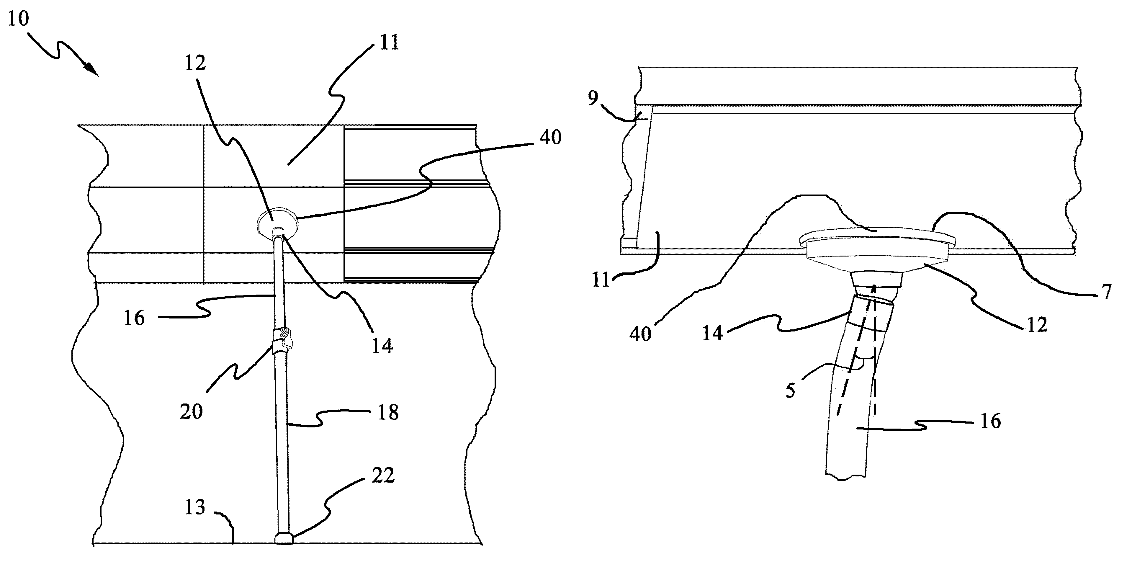
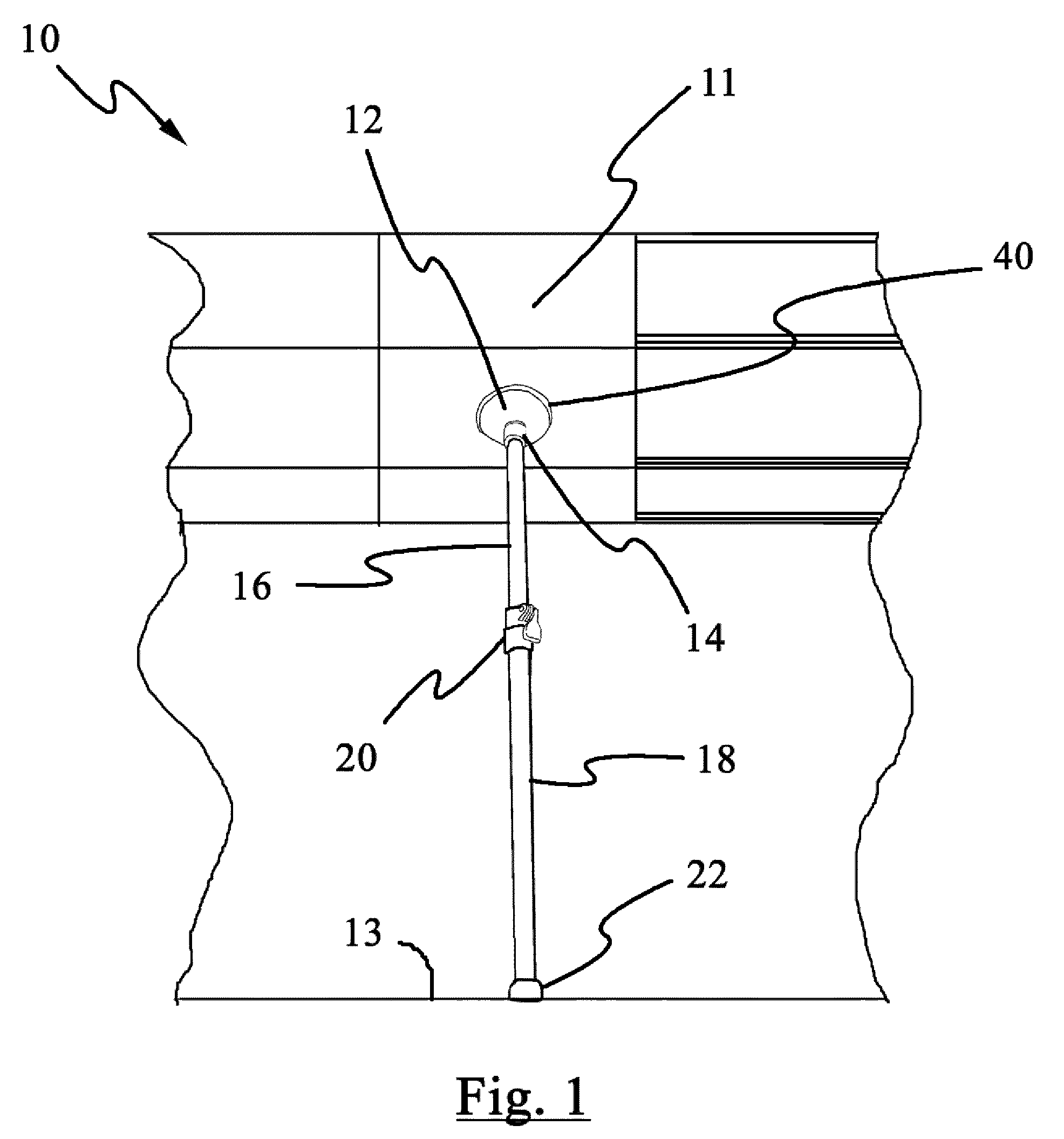
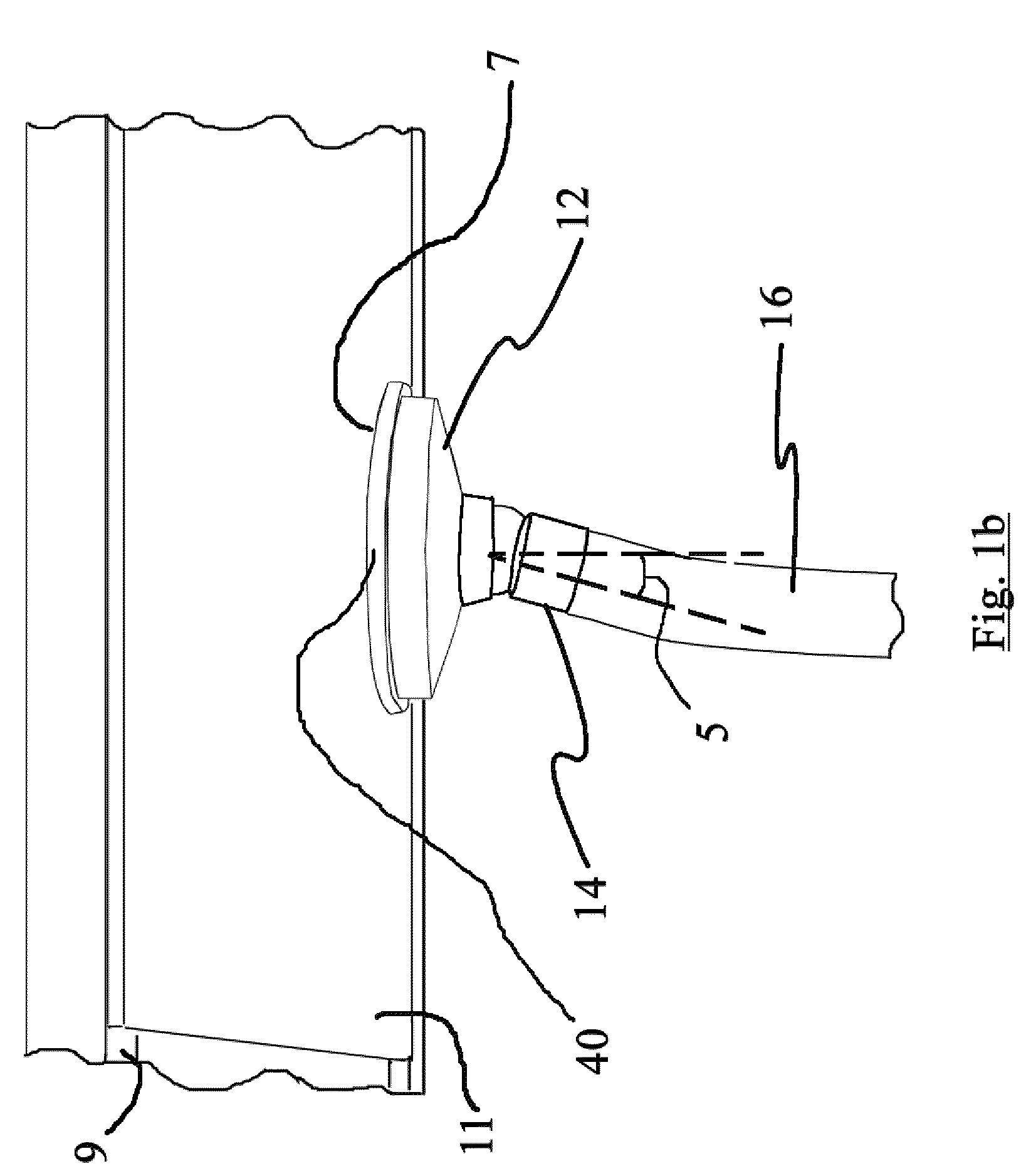
[0014]At least part of the pole section is made of a strong but flexible material that allows the poles to flex. It should be appreciated that the above described pole-ball-socket / flexible pole configuration allows the pressure-plate-surface to move relative to the pole section so that the pressure-plate-surface maintains a desired orientation relative to the construction-item surface.

Problems solved by technology

Such a system works, but it does require some coordination and is an awkward, unprofessional system.
Indeed, getting such boards up to ceiling heights can be a particularly difficult task without the right tools.
Such devices work well but are often too expensive to purchase for a do-it-yourselfer performing a one-time installation.
In addition, even for professionals such drywall lifts can be inconvenient as they take up a lot of room on / in the installer's vehicle / storage area and the time of use per board is greater than is necessary.
The Stewart device works well for its intended purpose but such a device is more bulky and complicated to use than it need be, in part due to the ridged design of the support shaft structure.
Such devices waste material as the jacks are used for that one installation task and then discarded.
One problem with such prior art devices relates, ironically, to the ridged nature of their construction.
Such devices work well but they are more complicated to use and require more time to use (adjust) per item than is necessary.

Method used


Image

  • Flexpole support apparatus
  • Flexpole support apparatus
  • Flexpole support apparatus

Examples


Embodiment Construction

[0028]Reference now will be made in detail to the embodiments of the invention, one or more examples of which are set forth below. Each example is provided by way of explanation of the invention, not limitation of the invention. In fact, it will be apparent to those skilled in the art that various modifications and variations can be made in the present invention without departing from the scope or spirit of the invention. For instance, features illustrated or described as part of one embodiment can be used on another embodiment to yield a still further embodiment. Thus, it is intended that the present invention covers such modifications and variations as come within the scope of the appended claims and their equivalents. Other objects, features, and aspects of the present invention are disclosed in or may be determined from the following detailed description. Repeat use of reference characters is intended to represent same or analogous features, elements or steps. It is to be unders...


PUM


Abstract

Disclosed is an improved apparatus for holding a construction item in a desired position while the construction item is being secured to a support structure. Embodiments of the apparatus comprise a pressure-plate configured with a pole-ball-socket, a pole-ball, and a flexible pole section. A plurality of pole sections may be used in a telescoping arrangement so that the apparatus may be used to lift a construction item to an elevated position. The pressure-plate defines a pressure-plate-surface configured for being associated with a surface of a construction item. The flexible pole section is then extended to move the construction item to a desired location (such as at ceiling height). Typically the pole section is held at an angle relative to a supporting surface (such as a floor) and then extended to a length about four inches longer than the distance from the supporting surface and said desired location. A side pressure is then applied to the pole section causing the pole section to flex and slide into position to support the construction item.

Description

CLAIM TO PRIORITY[0001]This application claims priority to provisional application 61 / 052,415 filed on May 12, 2008, the entire contents of which are incorporated herein by this reference for all that it discloses.FIELD OF THE INVENTION[0002]Embodiments of the present invention relate in general to the field of construction and are particularly useful as an installation aid for installing boards such as drywall and sheetrock.BACKGROUND OF THE INVENTION[0003]Many construction jobs require the use of support structures. One such example relates to the installation of various boards such as drywall, sheetrock, plywood, plasterboard, soffit plywood, durock, blueboard, densglass gold, and exterior drywall, particularly at ceiling levels. Do-it-yourselfers and even professionals have been known to attempt to hold drywall up to a ceiling using their heads before securing such boards to a support structure. Such a system works, but it does require some coordination and is an awkward, unprof...

Claims


Application Information

Patent Timeline
Patent Type & Authority Patents(United States)
IPC IPC(8): F16M13/00
CPCE04F21/1805E04H15/60
Inventor GRIDLEY, WILLIAMSCOTT, RANDALL B.
Owner BAM PATENTS LLC
Why Eureka
Try Eureka