Multi-sized wood and metal stake pulling device

a multi-sized, wood and metal stake technology, applied in the field of tools for can solve the problem that removing metal or wood stakes from concrete can be a particularly difficult task

Inactive Publication Date: 2012-06-19
BUSALACCHI FILIPPO M
View PDF30 Cites 10 Cited by
  • Summary
  • Abstract
  • Description
  • Claims
  • Application Information

AI Technical Summary

Problems solved by technology

Removing metal or wood stakes from concrete can be a particularly difficult task.

Method used


Image

  • Multi-sized wood and metal stake pulling device
  • Multi-sized wood and metal stake pulling device
  • Multi-sized wood and metal stake pulling device

Examples


Embodiment Construction

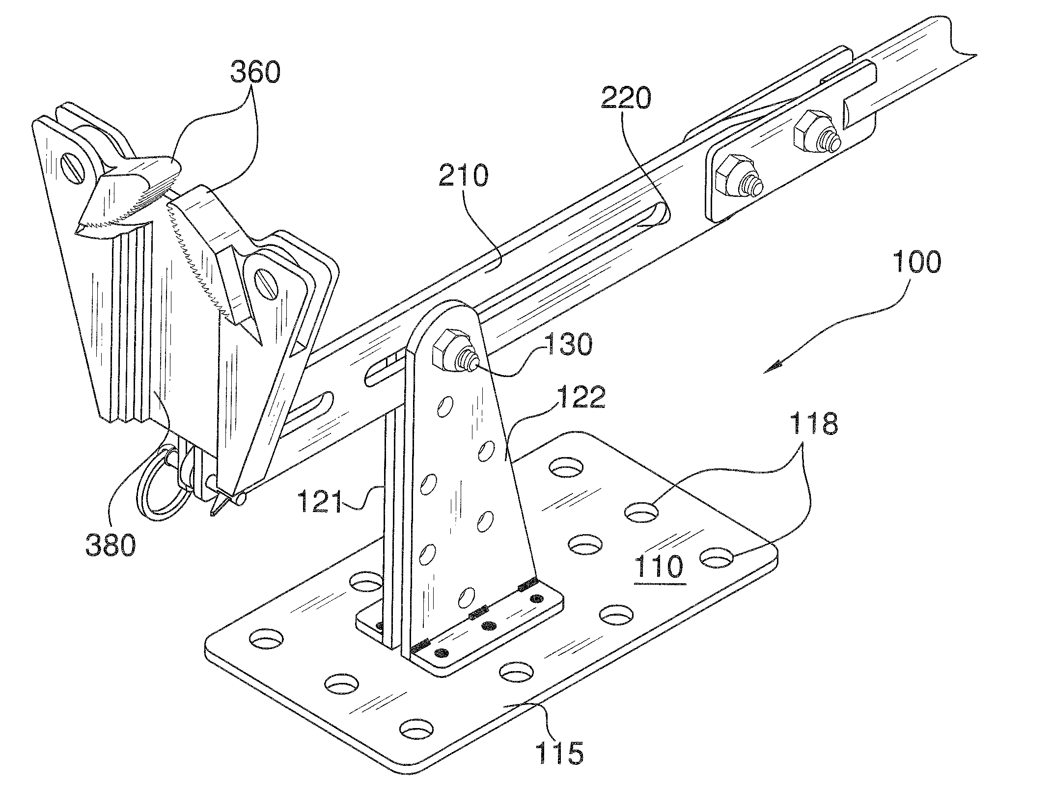
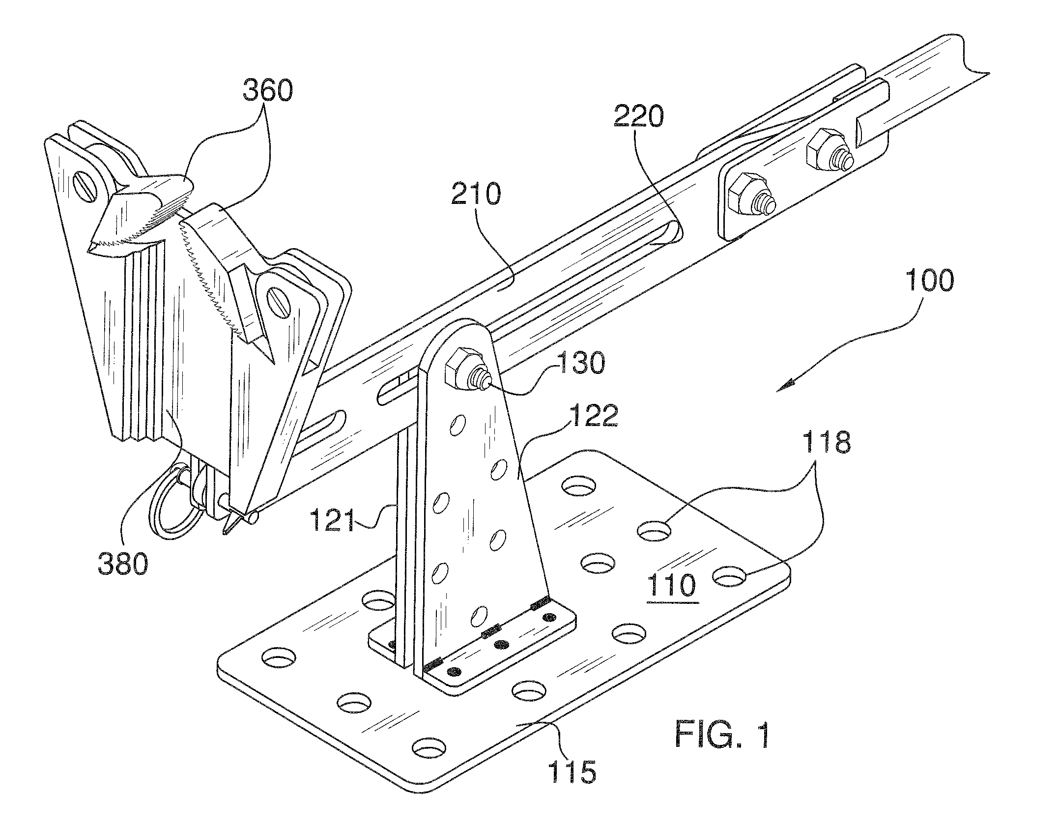
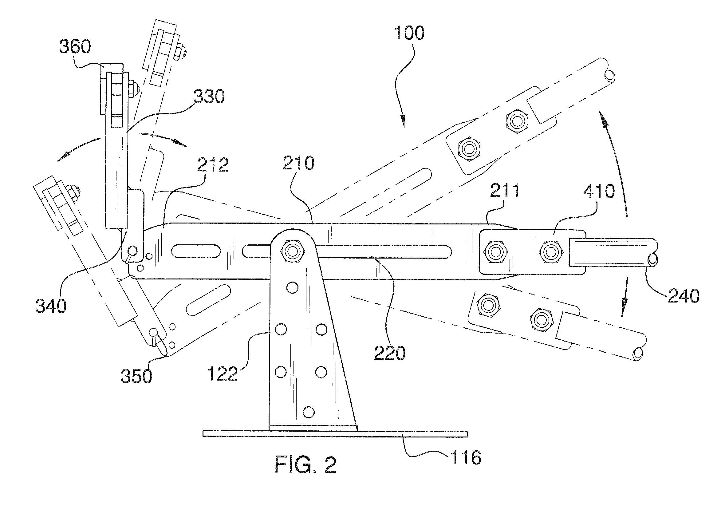
[0011]Referring now to FIGS. 1-7, the present invention features a stake pulling device 100 for removing metal or wood stakes 101, for example after completion of concrete work. Without wishing to limit the present invention to any theory or mechanism, it is believed that the stake pulling device 100 of the present invention is advantageous because it may help a user to remove stakes within a few seconds.

[0012]The stake pulling device 100 comprises a base plate 110 and support plates that together support an elongated pivot arm 210. The base plate 110 has a top surface 115 and a bottom surface 116. The base plate 110 is for placing on a ground surface. In some embodiments, one or more holes 118 are disposed in the base plate 110. The holes 118 may provide for a more stable positioning on a ground surface, for example if the ground is slightly uneven.

[0013]Extending upwardly from the base plate 110 is a first support plate 121 and a second support plate 122. The first support plate 1...


PUM


Abstract

A stake pulling device for removing a metal or a wood stake from concrete comprising a base plate for placing on a ground surface; a first support attached to the base plate extending upwardly; a pivot arm pivotally and slidably attached to the top end of the first support arm; a handle component disposed on a first end of the pivot arm; a grip plate attached to the second end of the pivot arm, wherein a stake cavity is disposed in an outer surface of the grip plate, the stake cavity is adapted for receiving the stake; and a pair of jaws pivotally attached to the grip plate above the stake cavity, the pair of jaws comprising teeth for gripping the stake, wherein the pair of jaws can pivot towards each other such that the teeth face each other or face away from each other.

Description

FIELD OF THE INVENTION[0001]The present invention is directed to a tool for removing stakes, more particularly to a tool for removing metal or wood stakes after completion of concrete work.BACKGROUND OF THE INVENTION[0002]Removing metal or wood stakes from concrete can be a particularly difficult task. The present invention features a wood and metal stake pulling device for providing a fast and easy means of removing metal or wood stakes from concrete.[0003]Any feature or combination of features described herein are included within the scope of the present invention provided that the features included in any such combination are not mutually inconsistent as will be apparent from the context, this specification, and the knowledge of one of ordinary skill in the art. Additional advantages and aspects of the present invention are apparent in the following detailed description and claims.BRIEF DESCRIPTION OF THE DRAWINGS[0004]FIG. 1 is a perspective view of the stake pulling device of t...

Claims


Application Information

Patent Timeline
Patent Type & Authority Patents(United States)
IPC IPC(8): B25C11/00E21B19/00
CPCB25C11/00
Inventor BUSALACCHI, FILIPPO M.
Owner BUSALACCHI FILIPPO M
Why Eureka
Try Eureka