Electrical connector assembly with EMI gasket

a technology of emi gasket and electrical connector, which is applied in the direction of coupling device connection, coupling protective earth/shielding arrangement, aperture leaage reduction, etc., can solve the problems of increasing the cost and/or complexity of emi gasket and/or the overall cost of the electrical connector assembly, and increasing the cos

Active Publication Date: 2012-06-19
TYCO ELECTRONICS LOGISTICS AG (CH)
View PDF14 Cites 20 Cited by
  • Summary
  • Abstract
  • Description
  • Claims
  • Application Information

AI Technical Summary

Problems solved by technology

For example, the adhesive may increase the cost and / or complexity of the EMI gasket and / or the electrical connector assembly overall.
Increased costs may arise, for example, from the cost of the adhesive itself and / or from the difficulty and / or time it takes to connect the ends of the cord together using the adhesive.

Method used


Image

  • Electrical connector assembly with EMI gasket
  • Electrical connector assembly with EMI gasket
  • Electrical connector assembly with EMI gasket

Examples


Embodiment Construction

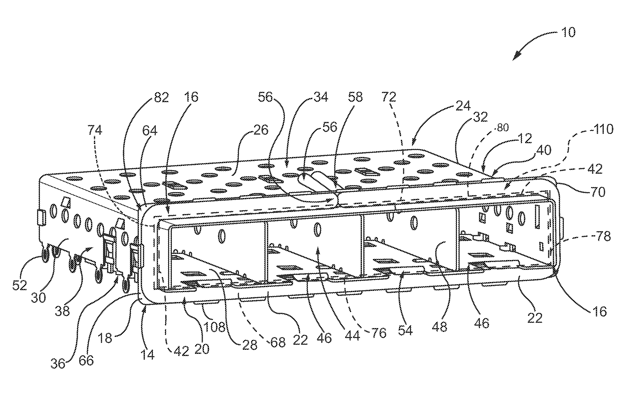
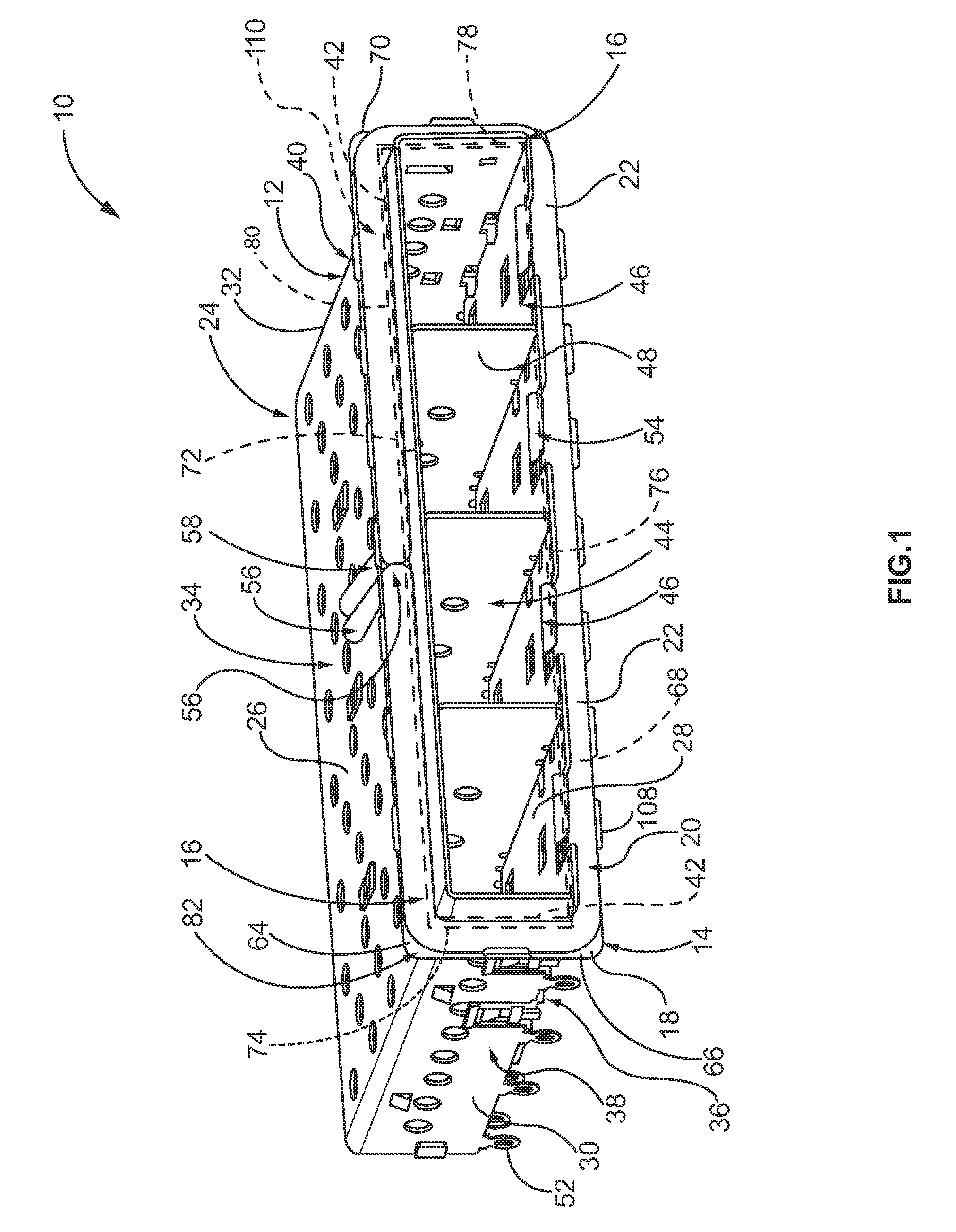
[0018]FIG. 1 is a perspective view of an exemplary embodiment of an electrical connector assembly 10. The assembly 10 includes an electrically conductive cage 12 having one or more electrical connectors (not shown) positioned therein and an electromagnetic interference (EMI) gasket assembly 14 mounted externally on an end 16 of the cage 12. The assembly 10 is configured to be positioned on a printed circuit (not shown) for electrically connecting one or more pluggable electrical components (not shown), such as, but not limited to, small form-factor pluggable (SFP) modules, to the printed circuit via the electrical connectors. The end 16 of the cage 12 is configured to be mounted, or received, within an opening (not shown) of a panel (not shown) that is adjacent the printed circuit. For example, the panel may be a wall of the housing of a device (not shown), such as, but not limited to, a computer, that includes the printed circuit. In such an example, the electrical connector assemb...


PUM


Abstract

An electrical connector assembly includes an electrically conductive cage having a cage end configured for mounting in a panel opening. The cage has a compartment for receiving a pluggable electrical component therein. The cage end has a circumference defined by an exterior surface of the cage. A retention frame extends over the cage end along at least a portion of the circumference. The retention frame includes a gasket side and a rear side. A retention opening extends through the gasket and rear sides of the retention frame. An EMI gasket is mounted on the cage end. The EMI gasket includes a length of electrically conductive cord having opposite cord ends. The cord is wrapped externally around the cage end forming a continuous band that engages the exterior surface of the cage along at least a portion of the circumference. The cord extends along and engages the gasket side of the retention frame and the cord ends extend through the retention opening and along the rear side of the retention frame.

Description

BACKGROUND OF THE INVENTION[0001]The subject matter described and / or illustrated herein relates generally to electrical connector assemblies, and more particularly, to electrical connector assemblies for pluggable electrical components.[0002]Some known electrical connector assemblies include a metal cage having one or more ports for receiving pluggable electrical components, such as small form factor pluggable (SFP) modules. The ports enable the pluggable electrical components to plug into an electrical connector that is held within the cage and electronically connected to a host circuit board. An end of the cage that includes the ports is typically held within a panel of a housing that contains the host circuit board therein. For example, the housing may be the housing of a computer that includes the host circuit board. An electrically conductive gasket may extend circumferentially around the end of the cage. The gasket is engaged between the panel and the cage and facilitates cont...

Claims


Application Information

Patent Timeline
Patent Type & Authority Patents(United States)
IPC IPC(8): H05K9/00
CPCH01R13/6584H05K9/0015H05K9/0018H05K9/0058H01R13/659
Inventor WERTZ, JR., ROBERT HARRISONSCHMITT, MATTHEW RYANSHIFFLER, JAMES CHARLESDRESCHER, SCOTT P.
Owner TYCO ELECTRONICS LOGISTICS AG (CH)
Why Eureka
Try Eureka