Electrostatographic printing machine

a printing machine and electrographic technology, applied in the field of electrographic printing machines, can solve the problems of variable image performance, mechanical failure of the device, and inability to achieve highly resolved developed images, so as to reduce the overall running cost of the electrographic printing system, reduce manufacturing costs, and simplify the design of the print engine

Inactive Publication Date: 2012-06-26
XEIKON
View PDF5 Cites 0 Cited by
  • Summary
  • Abstract
  • Description
  • Claims
  • Application Information

AI Technical Summary

Benefits of technology

[0017]It has been found that the electrostatic charging device acting onto the development member which also works as a carrier liquid displacement device acting upon the thin layer of liquid toner on the development member can supply the voltage differential between the rollers to assist in moving the electrostatically charged liquid toner particles to the latent image on the imaging member. A voltage with respect to machine earth is induced onto the development member and the toner supply roller and the metering roller also have a voltage with respect to machine earth induced onto them by, it is assumed, conduction through the carrier film during use. The amount of the induced voltage can be controlled on each roller of member by the respective voltage regulating or controlling means. Additionally, it has been found that by using a voltage regulating or control means as described herein, allows for the significant lowering of the surface voltage potential on the imaging member without the loss of image quality or increased background noise; indeed, the image quality and image density increase. The lowering of the latent image surface voltage on the imaging member has the additional benefit of decreasing potential photoconductor fatigue which is associated with high charging voltages. The lowering of the surface potential on the imaging member increases the useable life of the photoconductor. Further, the simplified system described herein, allows for significantly reduced hardware and maintenance costs, especially in the office automation area where the total cost of ownership can be significantly reduced with the present invention.
[0087]In contrast, in a traditional resilient type of contact, what is being primarily controlled is the contact force. The development system of the present invention is not dependent on the force between the rollers, but strictly on the nip width. Also, having an interference fit in an HVT high speed print engine provides stable printing and prevent vibration of the rollers that could be originate from a resilient engagement. This can in fact lead, for example, to banding on the developed image due to the instability of the rollers caused by the resilient urging. Finally, a further advantage is that it is simpler to create a controlled contact between rollers by adjusting distances, rather than changing the force between the rollers.

Problems solved by technology

For example the performance of dry powder toners is very susceptible to environmental conditions, influencing, for example, charge stability, and therefore giving rise to variable image performance.
Also, the large particle size of dry powder toners is a major contributing factor in not allowing the achievement of highly resolved developed images.
Other objections are related to the problem of dusting.
Dust or fine or small particles of toner are prone to escape from the developer, and these deposit onto any surface both within and outside the printing device, causing mechanical failures within the device and environmental problems outside the device.
This problem becomes severe when such dry powder printing devices are run at higher speeds.
In addition, achieving high resolution with dry powder toners at higher speeds is difficult due to the fact that the dusting problem is further exacerbated by the need to reduce dry toner particle size to a level which will allow acceptable resolution at high speeds, which further compounds the difficulty and dangers in handling such fine powders.
Dry powder systems therefore can not in practice achieve high resolution images that are usually associated with analogue printing methods such as off-set and gravure printing.
Other disadvantages include cost of the general maintenance of the printer and cost of the dry powder toner.
Furthermore, the liquid toners for these systems are operationally and chemically stable, particularly to environmental changes due to buffering properties of the carrier liquid, thus exhibiting a particularly long shelf-life.
Maintaining a uniform dispersion of the marking particles can be difficult in a low viscosity toner system.
Furthermore, low volume of solids in the toner increases the amount of toner required to develop a given latent image.
Such an arrangement of the development region has several drawbacks, such as a reduced strength and uniformity of the electric field in the development gap, and additional complexity in the design required to maintain a constant gap in the printing direction, as well as across the page.
This usually results in reduced development efficiency, edge effects and non-uniform solid fill.
Devices using such liquid electrographic printing can also have some objectionable problems.
The main problem is in regard to the carrier liquid carry-out.
Such carrier liquid subsequently evaporates during image fusing, giving rise to atmospheric pollution and also adding significantly to production costs.
A further disadvantage of such liquid toning is the tendency for deposition of colouring matter in non-image or background areas which results in a general discolouration of the copy, normally referred to as background staining or fog.

Method used


Image

  • Electrostatographic printing machine
  • Electrostatographic printing machine
  • Electrostatographic printing machine

Examples


Embodiment Construction

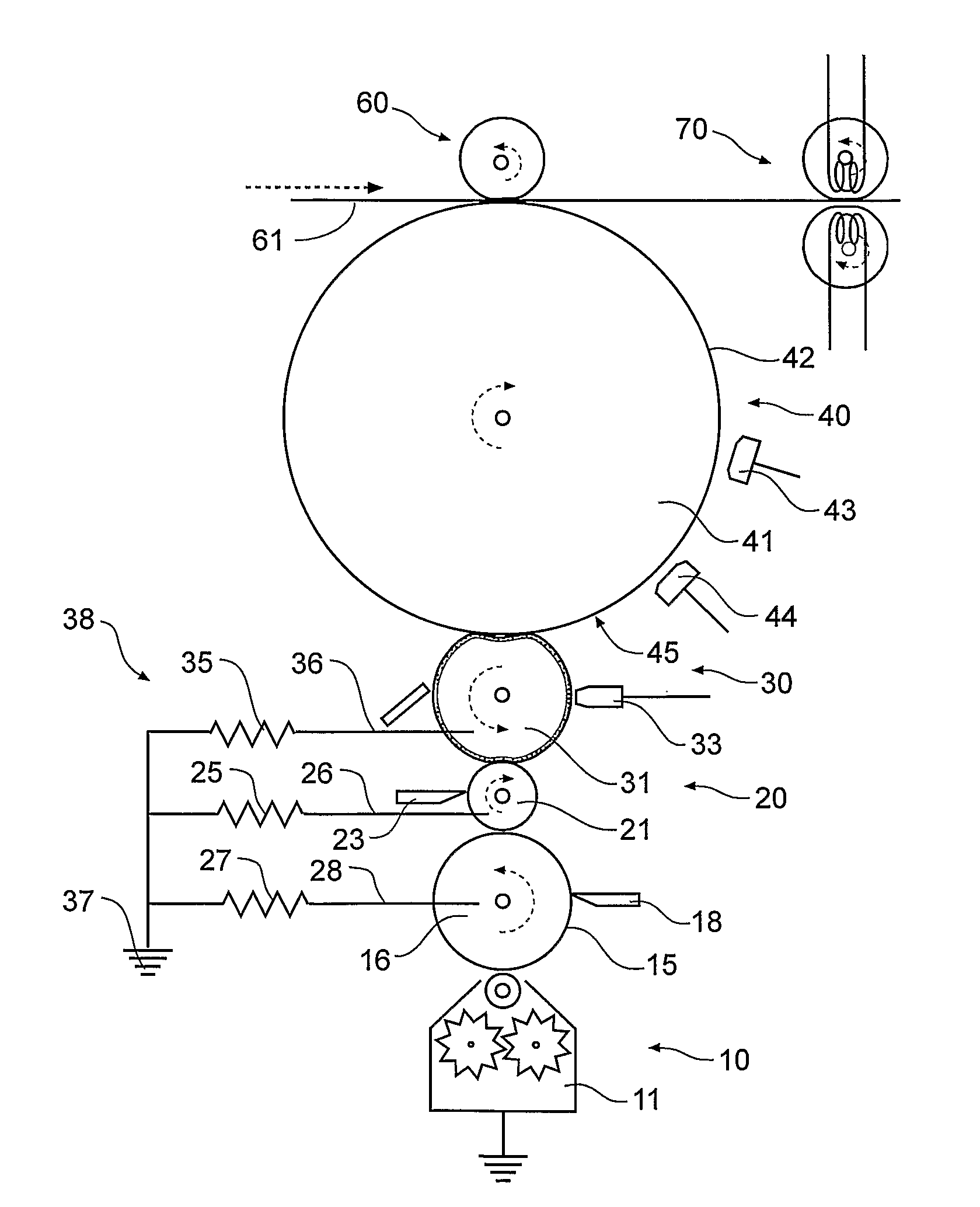
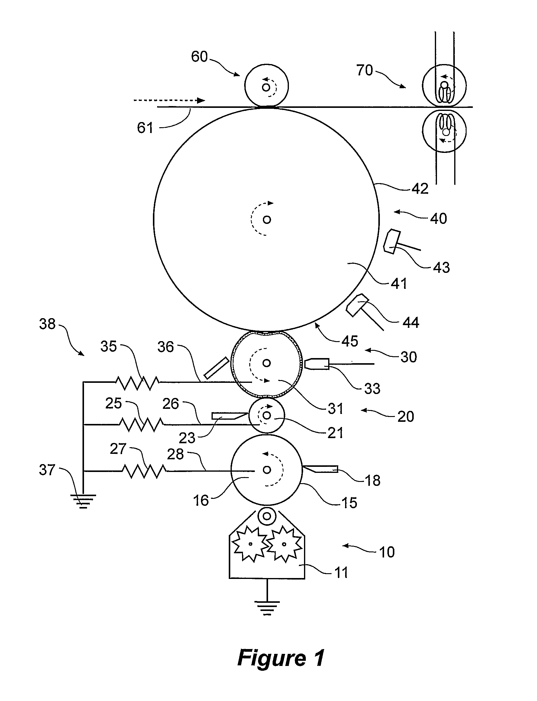
[0101]Now looking at FIG. 1, this drawing shows a schematic electrostatic printing apparatus according to the present invention.

[0102]In FIG. 1, the schematic electrostatic printing process generally has a toner supply stage 10, a toner metering apparatus 20, a development stage 30, an imaging stage 40, a transfer to substrate stage 60 and a fixing stage 70.

[0103]Toner is supplied by the toner supply stage 10 from a toner tank 11 to a pick-up roller or toner supply roller 16. The pick-up roller or toner supply roller 16 has a doctor blade 18 bearing against it to provide an even thin layer of high viscosity toner on the pick-up roller or toner supply roller 16.

[0104]The pick-up roller or toner supply roller 16 is spaced apart from a metering roller 21. The metering roller 21 has a pattern of recesses on its surface and a doctor blade 23 bearing against the metering roller 21 scrapes essentially all of the high viscosity toner off the metering roller 21 except that toner which is wit...


PUM


Abstract

An electrostatographic printing machine has a liquid toner supply chain incorporating at least a toner supply device (10), a metering roller (21) and a development member (31) and an image carrying member (41). An electrostatic charging device (33) acts onto the development member to impress an electrostatic charge onto the development member and to induce a voltage thereon with respect to a machine electrical common earth potential. The toner supply roller, the metering roller and the developer member are each electrically connected to the machine electrical common earth potential (37) via a respective voltage regulating or controlling means (25, 27, 35) to regulate or control induced voltages on each of the toner supply roller, the metering roller and the developer member.

Description

CROSS REFERENCE TO RELATED APPLICATIONS[0001]The present application is a National Stage Application claiming the priority of co-pending PCT Application No. PCT / AU2008 / 000168 filed Feb. 11, 2008, which in turn, claims priority from Australian Application Serial. No. 2007900689, filed Feb. 12, 2007. Applicants claim the benefits of 35 U.S.C. §120 as to the PCT application and priority under 35 U.S.C. §119 as to the said Australian application, and the entire disclosures of both applications are incorporated herein by reference in their entireties.FIELD OF INVENTION[0002]This invention relates to electrostatography, and more particularly to a method and means for image development utilising highly viscous, highly concentrated liquid developers.BACKGROUND OF THE INVENTION[0003]A non-impact printing process can be simply defined as a process which uses an electronic, electric, magnetic or optical means to produce characters as opposed to a mechanical means. Of the non-impact printing pr...

Claims


Application Information

Patent Timeline
Patent Type & Authority Patents(United States)
IPC IPC(8): G03G15/06
CPCG03G15/0806
Inventor MAO, MINGHUA
Owner XEIKON
Why Eureka
Try Eureka