Method for dimming electroluminescent display

a technology of electroluminescent display and dimming method, which is applied in the direction of instruments, static indicating devices, etc., can solve the problems of display quality that is perceived by the end user as low, differences in luminance, and inadvertent pattern creation, so as to reduce burn-in, reduce luminance, and reduce cost

Active Publication Date: 2017-03-21
GLOBAL OLED TECH
View PDF17 Cites 0 Cited by
  • Summary
  • Abstract
  • Description
  • Claims
  • Application Information

AI Technical Summary

Benefits of technology

[0017](d) transforming the input image signals for a second frame to a plurality of second drive signals using a dimming transform that operates on the input image signals for each frame to provide a peak frame luminance value for the second frame wherein the dimming transform includes an exponential function, whereby the second frame has reduced luminance to reduce burn-in.
[0018]The present invention provides a low cost method for rapidly manipulating the luminance of a display. This method permits the luminance of a display to be manipulated over a large range without a significant loss in image quality, enabling more rapid and larger dimming changes. By dimming EL displays in this way, the likelihood of image stick and power is reduced. In some embodiments, this is achieved without reducing the detail within a shadow range of the displayed images. The present invention recognizes that the human eye responds to light and adapts as a logarithmic detector. By better matching the dimming function of the display to the adaptation curve of the human eye, more rapid dimming can be implemented without the introduction of visible artifacts. Further, this invention recognizes that information is lost when dimming displays to reduce image stick because the function relating input to output luminance is typically linear while the human eye responds to light as a logarithmic detector and therefore adjusts the contrast of the image as the luminance of the display is reduced to provide a higher quality image and to further reduce burn-in.

Problems solved by technology

Unfortunately, as these emitters convert current to light they typically degrade and this degradation is a function of the current that is provided to each emitter.
Therefore each emitter will likely have a different amount of degradation and this difference in degradation results in differences in luminance when the emitters are driven with the same current to produce a uniform image.
As a result, inadvertent patterns are created when the display is turned on due to this difference in luminance uniformity.
These patterns can be distracting and cause the display to be perceived by the end user as low in quality or, under extreme conditions, unusable.
This problem is not unique to OLED but instead arises in all known emissive displays, including CRTs and plasma displays, and can be exhibited by non-emissive displays, such as liquid crystal displays.
While this method satisfies the requirement that it will reduce the image stick artifact, the method provides a very rapid change in luminance, which will be quite noticeable to the user and by controlling the analog circuit in this fashion, there is little control of the appearance of the image after its luminance is reduced.
Once again, the method permits static images to be dimmed, however, by changing the gain value, there is little ability to control the appearance of the final image after its luminance is reduced.
However, Holtslag does not provide a detailed description of the method used to reduce visibility.
Unfortunately, the implementation of algorithms for object detection within a display driver is prohibitively expensive and does not provide a practical solution to maintaining the quality of the image as the luminance of the display is reduced to avoid image stick.
Further, such methods are very difficult to employ in natural images, which have nearly continuous tonal levels and it is impossible to maintain adequate contrast between every tonal level such that the difference in tonal levels are visible.
Further, the images constantly lose shadow detail as the image is dimmed.

Method used


Image

  • Method for dimming electroluminescent display
  • Method for dimming electroluminescent display
  • Method for dimming electroluminescent display

Examples


Embodiment Construction

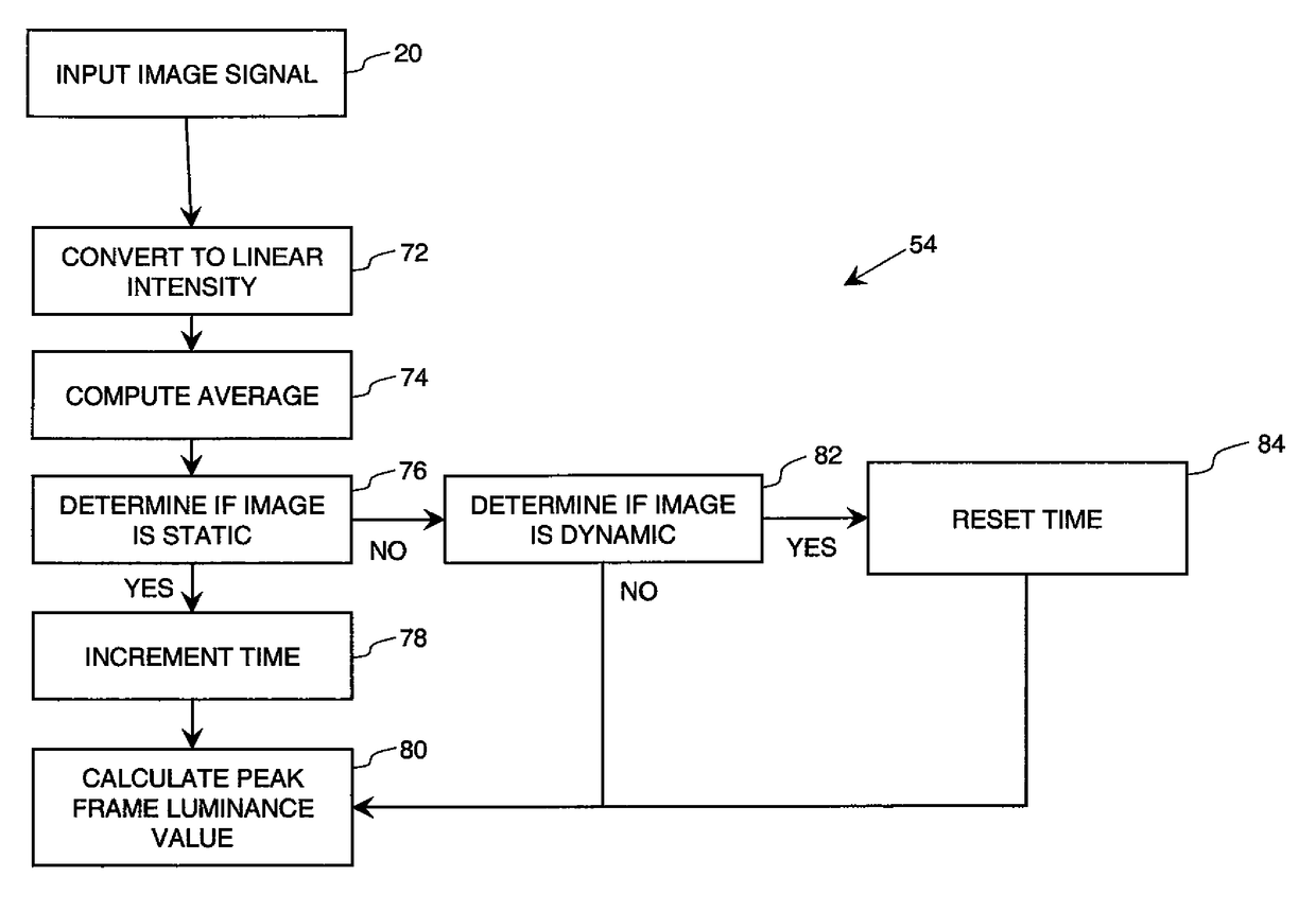
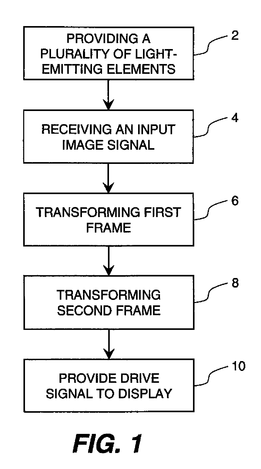
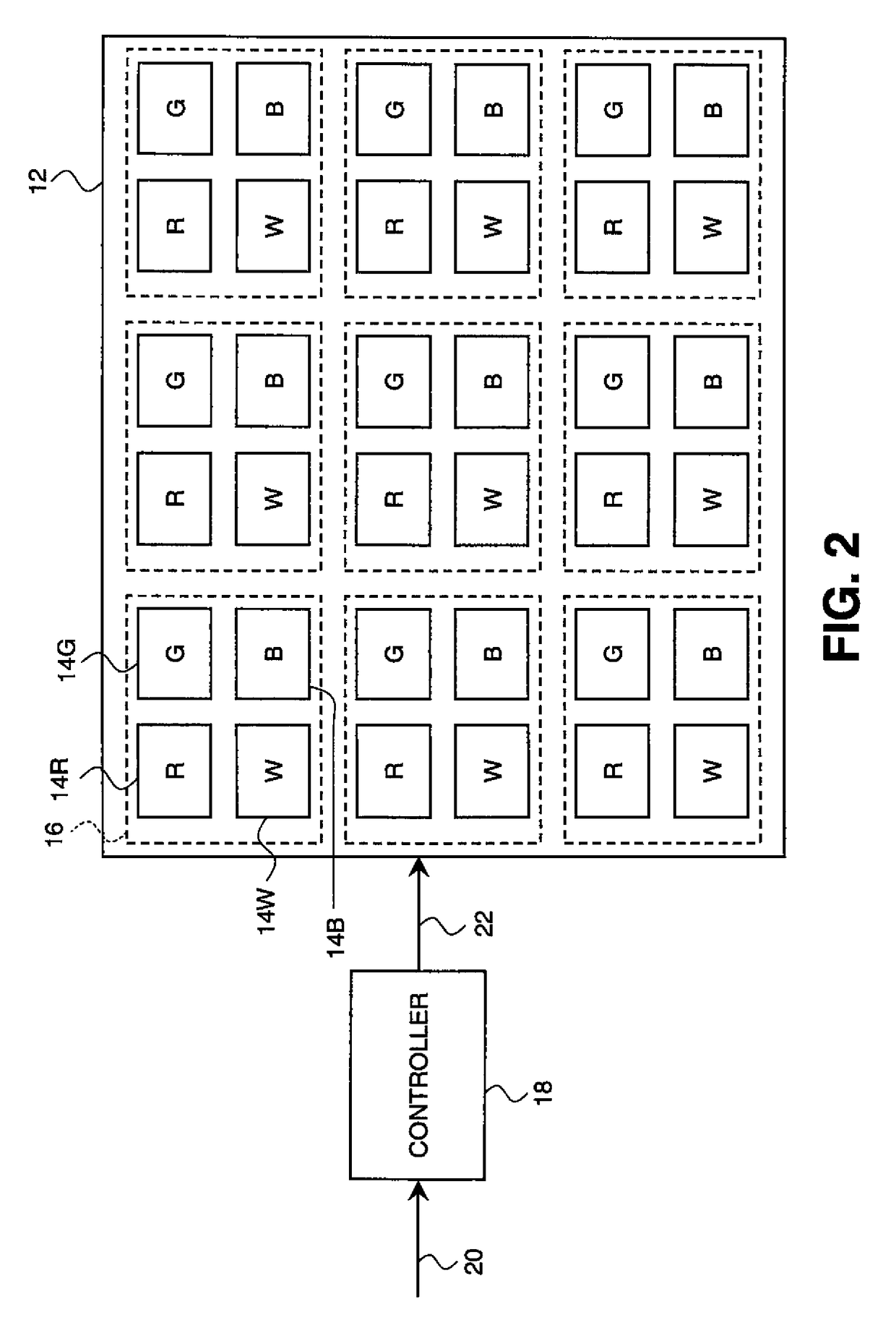
[0027]The need is met by providing a method for controlling an electroluminescent display to produce first and second images for display wherein the second image has reduced luminance to reduce burn-in on the display. As shown in FIG. 1, an electroluminescent (EL) display is provided 2 including a plurality of EL emitters, the luminance of the light produced by each EL emitter being responsive to a respective drive signal. A respective input image signal is received 4 for each EL emitter for each of a plurality of frames. The input image signals for a first frame are transformed 6 to provide a plurality of first drive signals to produce an image on the display. Further, the input image signals for a second frame are transformed 8 to a plurality of second drive signals using a dimming transform that operates on the input image signals for each frame to provide a peak frame luminance value for the second frame wherein the dimming transform includes an exponential function, whereby the...


PUM


Abstract

A method for controlling an electroluminescent display to produce first and second images for display wherein the second image has reduced luminance to reduce burn-in on the display, includes providing the electroluminescent (EL) display having a plurality of EL emitters, the luminance of the light produced by each EL emitter being responsive to a respective drive signal; receiving a respective input image signal for each EL emitter for each of a plurality of frames; transforming the input image signals for a first frame to provide a plurality of first drive signals to produce an image on the display; and transforming the input image signals for a second frame to a plurality of second drive signals using a dimming transform that operates on the input image signals for each frame to provide a peak frame luminance value for the second frame wherein the dimming transform includes an exponential function.

Description

CROSS REFERENCE TO RELATED APPLICATION[0001]Reference is made to commonly-assigned, co-pending U.S. patent application Ser. No. 12 / 271,355, filed concurrently herewith entitled “Tonescale Compression For Electroluminescent Display” by Miller et al, the disclosure of which is incorporated by reference herein.FIELD OF THE INVENTION[0002]The present invention relates to electroluminescent display systems. Particularly, the present invention provides a method for rapidly dimming an electroluminescent display while in a visually indistinguishable manner. Further embodiments are provided which maintain shadow detail.BACKGROUND OF THE INVENTION[0003]Many display devices exist within the market today. Among the displays that are available are thin-film, coated, electroluminescent (EL) displays, such as organic light-emitting diode (OLED) displays. These displays can be driven using an active matrix or passive matrix back plane. Regardless of the technology that is applied, these display dev...

Claims


Application Information

Patent Timeline
Patent Type & Authority Patents(United States)
IPC IPC(8): G09G3/32G09G3/34
CPCG09G3/3208G09G2300/0452G09G2320/046G09G2320/066G09G2320/103G09G2330/045G09G2360/16
Inventor MILLER, MICHAEL E.WHITE, CHRISTOPHER J.
Owner GLOBAL OLED TECH
Why Eureka
Try Eureka