Spatially encoded phase-contrast MRI

a phase-contrast, spatial encode technology, applied in the direction of magnetic measurement, measurement using nmr, instruments, etc., can solve the problems of inhomogeneity of field, affecting the detection accuracy of mri data, and reducing acquisition time, so as to avoid the disadvantages of conventional techniques, reduce acquisition time, and reduce the effect of acquisition tim

Active Publication Date: 2016-12-27
MAX PLANCK GESELLSCHAFT ZUR FOERDERUNG DER WISSENSCHAFTEN EV
View PDF15 Cites 1 Cited by
  • Summary
  • Abstract
  • Description
  • Claims
  • Application Information

AI Technical Summary

Benefits of technology

[0015]The objective of the invention is to provide an improved method of collecting MR data, in particular for MRI of an object with a predetermined spin density, e. g. for medical imaging purposes, which is capable of avoiding disadvantages of conventional techniques. In particular, the objective is to provide a method of collecting MR data for 3D MRI of an object with a very much (e.g., 100-fold) reduced acquisition time which further enables a continuous acquisition of 3D MR images with reduced acquisition times, thus allowing the provision of an image sequence with a practical frame rate, in particular without a loss in image quality. Furthermore, the objective of the invention is to provide an improved control device being adapted for collecting MR data, in particular for 3D MRI of an object with reduced acquisition time and to a MRI device, in particular being adapted for conducting the method of collecting MR data and imaging of the object.SUMMARY OF THE INVENTION
[0022]Thus, the inventors have found that the 3D MR data collection can be essentially facilitated and considerably accelerated, if the object is not imaged with conventional spatial resolution along the at least one selected spatial dimension, but rather the mean spin density position of the object along said spatial dimension is calculated. Instead of the typical 256 2D acquisitions (i.e., 256×256 repetition intervals) needed for conventional 3D MRI, the teaching according to the invention requires no more than only two 2D acquisitions which reduces the total acquisition time by more than a factor of 100. Although there is an apparent loss of information with respect to object features along the selected spatial dimension, it has been found that this apparent loss of information can be tolerated for a wide variety of objects and / or imaging tasks. As an example, if the object has a negligible extension along the selected spatial dimension compared with the remaining dimensions, e.g. if the object has the shape of a layer, line or dot, the calculation of the mean spin density position is sufficient for characterizing the location of an object voxel in space. As a further example, if the object's spin density has a pre-known geometric extension along the selected spatial dimension, the calculation of the mean spin density position is sufficient for characterizing the object in space as well. Even in the general case, that no information is available about the object shape and the intensity data representing the mean quantity of the object spin along the selected spatial dimension is collected only, the inventive MR data collection delivers useful projection data along the selected spatial dimension.
[0028]With the first embodiment of the invention, a predetermined projection plane is selected, and the predetermined spatial dimension is oriented perpendicular to the projection plane. Preferably, the projection plane is selected such that the average extension (thickness) of the object layer perpendicular to the projection plane is minimized. The MR signal acquisition step, using the signal acquisition device, includes acquiring two 2D MR images representing projections of the object onto the projection plane in object space with said different settings of spatially encoding phase-contrast gradients along the spatial dimension perpendicular to said projection plane. A plurality of said mean spin density positions of said object along said spatial dimension are calculated for a plurality of different locations of the object layer covering the projection plane, thus resulting in the determination (reconstruction) of a 3D image of the object. As a main advantage of the first embodiment, when mapping curved 2D structures or surface layers in 3D space, the inventive method reduces the dimension of the necessary MRI acquisition process from three to two, which accelerates the acquisition by two orders of magnitude in comparison to conventional 3D MRI.
[0029]Preferably, the RF pulse and gradient control device is configured such that one of said at least two spatially encoding phase-contrast gradients is applied in a first repetition interval comprising a said sequence of RF and gradient pulses with the other of said two gradients being applied in the immediately following repetition interval, or one of said at least two spatially encoding phase-contrast gradients is applied in all repetition intervals associated to a first image acquisition with the other gradient being applied in all repetition intervals associated to a second image acquisition. According to the first alternative, the different spatially encoding phase-contrast gradients can be consecutively set in immediately successive repetitions of said RF pulses and magnetic field gradients. With this variant of the first embodiment, advantages can be obtained for MRI of objects moving with high velocity. Alternatively, the different spatially encoding phase-contrast gradients can be consecutively set in successive image acquisitions with said RF pulses and magnetic field gradients. This variant may have advantages in terms of a twofold higher frame rate when applying a sliding window technique to the calculation of phase-contrast maps that are shifted by only one image acquisition.
[0030]Another important advantage of the first embodiment of the invention results from the fact that any available imaging technique, in particular data collection and image reconstruction procedures can be used for acquiring the two 2D MR images. Thus, according to preferred variants of the invention, the RF pulses and magnetic field gradients can be adapted for Cartesian frequency- and phase-encoding, radial encoding, spiral encoding or other non-Cartesian encoding. Furthermore, the RF pulses and magnetic field gradients may be controlled such that, for example, a low-flip angle gradient-echo MRI sequence, a spin-echo MRI sequence, a stimulated echo MRI sequence, or an echo-planar imaging sequence is provided. According to a particularly preferred embodiment of the invention, the low-flip angle gradient-echo MRI sequence comprises an undersampled radial FLASH sequence. Thus, the image acquisition speed can be even more increased.
[0039]According to a particularly preferred application of the invention, in particular for imaging purposes, the inventive MR data collection is repeated a plurality of times and a plurality of successive images is reconstructed so that an image sequence is obtained. According to preferred embodiments of the invention, a repetition rate is selected, so that a moving object is imaged with temporal resolution of better than 50 ms, in particular better than 30 ms or even better than 10 ms, like 5 ms or below. In particular, if combined with undersampled radial FLASH and image reconstruction by regularized nonlinear inversion, spatial phase-contrast MRI allows for 3D mapping of dynamic surface structures in real time. First examples obtained by the inventors include 3D MRI movies of the acting human hand at a temporal resolution of 50 ms. Moreover, 3D MRI movies of a rapidly rotating test object (banana) were obtained at 5 ms resolution or 200 frames per second. In conclusion, 3D spatial phase-contrast MRI of 1D or 2D structures is respective four or two orders of magnitude faster than conventional 3D MRI.

Problems solved by technology

Nevertheless, the monitoring of dynamic processes in real time remained hampered in particular due to the need for still relatively long measuring times of several hundreds of milliseconds for images with a reasonable spatial resolution.
For example, so-called single-shot gradient-echo sequences such as echo-planar imaging and spiral imaging are prone to geometric distortions or even local signal losses that are caused by their inherent sensitivity to off-resonance effects, tissue susceptibility differences, and magnetic field inhomogeneities, which are unavoidable in many parts of the body.
Complementary, single-shot MRI sequences that employ radiofrequency-refocused spin echoes or stimulated echoes and therefore are free from such problems, lead to a pronounced radiofrequency (RF) power absorption with the risk of local tissue heating or suffer from a compromised signal-to-noise ratio, respectively.
[5], disadvantages with regard to the image quality may result from the fact that the total acquisition time per image remains unchanged, that is as long as 250 ms.

Method used


Image

  • Spatially encoded phase-contrast MRI
  • Spatially encoded phase-contrast MRI
  • Spatially encoded phase-contrast MRI

Examples


first embodiment

3D MRI of 2D Structures (First Embodiment of MR Data Collection)

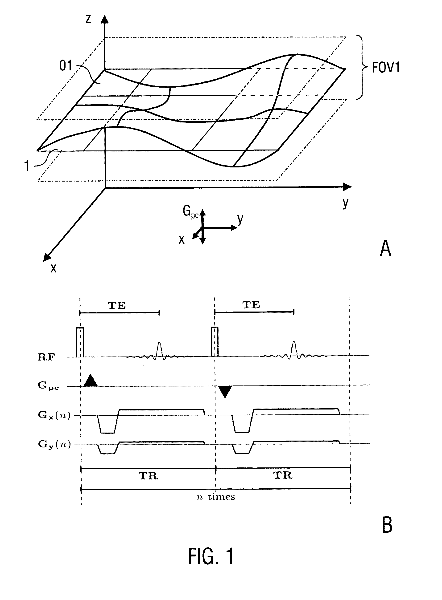
[0045]According to the first embodiment of the invention, an object layer O1 is imaged as described in the following with reference to FIGS. 1A and 1B. The object layer O1 has a spin density distributed along a curved surface, which essentially extends parallel to the x-y-plane. Minimum extensions of the object layer O1 occur in the z-direction. Accordingly, the z-direction is selected as the predetermined spatial dimension for applying the phase-contrast gradients Gpc, and a plane parallel to the x-y-plane is selected as a projection plane 1. For MRI of the object layer O1, two 2D MR images representing projections of the object layer O1 onto the projection plane 1 in object space are collected with different settings of the spatially encoding phase-contrast gradients along the z-direction. The phase difference between MR signals acquired with the two different phase-contrast gradients represents the mean spin density ...


PUM


Abstract

A method of collecting magnetic resonance data for imaging an object with a predetermined spin density being arranged in a static magnetic field, comprises the steps subjecting said object to at least one radiofrequency pulse and magnetic field gradients for creating spatially encoded magnetic resonance signals, including at least two settings of spatially encoding phase-contrast gradients differently encoding the phase of said magnetic resonance signals in at least one field of view in a predetermined spatial dimension, acquiring at least two magnetic resonance signals, each with one of said at least two settings of different spatially encoding phase-contrast gradients, and determining at least one mean spin density position of said object along said spatial dimension by calculating the phase difference between said signals. Furthermore, a control device and a magnetic resonance imaging (MRI) device implementing the method are described.

Description

FIELD OF THE INVENTION[0001]The present invention relates to a method of collecting magnetic resonance (MR) data, in particular for MR imaging of an object with a predetermined spatial spin density. Furthermore, the invention relates to a control device being adapted for collecting MR data, in particular for MR imaging (MRI) of an object, and to a MRI device, in particular being configured for implementing the above method. Applications of the invention cover the field of MRI, in particular medical MRI (e.g., three-dimensional (3D) or interventional imaging) or non-medical investigations in natural sciences (e. g., investigations of a workpiece or a dynamic process).BACKGROUND OF THE INVENTION[0002]For describing the background of the invention, particular reference is made to the following publications.[0003][1] Moran P R. A flow velocity zeugmatographic interlace for NMR imaging in humans. Magn. Reson. Imaging 1982; 1:197-203.[0004][2] Van Dijk P. Direct cardiac NMR imaging of hea...

Claims


Application Information

Patent Timeline
Patent Type & Authority Patents(United States)
IPC IPC(8): G01R33/561G01R33/563G01R33/28G01R33/48
CPCG01R33/48G01R33/4826G01R33/286G01R33/5613G01R33/56316G01R33/56325
Inventor FRAHM, JENSMERBOLDT, KLAUS-DIETMARUECKER, MARTINVOIT, DIRK
Owner MAX PLANCK GESELLSCHAFT ZUR FOERDERUNG DER WISSENSCHAFTEN EV
Why Eureka
Try Eureka