
Leg lift mechanism for electric bed or chair

a technology leg lift, which is applied in the field of electric bed or chair, can solve the problems of insomnia, lack of rest, and user discomfort, and achieve the effect of enhancing user comfor

Active Publication Date: 2012-07-03
RUOEY LUNG ENTERPRISE
View PDF3 Cites 9 Cited by
  • Summary
  • Abstract
  • Description
  • Claims
  • Application Information

AI Technical Summary

Benefits of technology

"The present invention provides a leg lift mechanism for an electric bed or chair that has multiple pivotal movements for enhancing a user's comfort. The mechanism includes a bed frame, a primary frame, a driver, and a link rod. The link rod is pivotally connected with the bed frame and mounted with the second angle bracket, and a support portion abutted against the third structural component. The driver includes a positioning portion pivotally connected with the first structural component through a first pin inserted through a securing aperture of the first structural component, and an extendable rod having a through hole aligned with a sliding slot of the first angle bracket. The link rod is pivotally connected with the extendable rod of the driver by a control pin inserted into the sliding slot of the first angle bracket and a second aperture of the link rod. The mechanism allows for different movements of the primary frame by pushing the link rod with the extendable rod of the driver, which causes the lift bracket to pivotally move upwards and the third structural component to be lifted. The technical effect of the invention is to provide a more comfortable and relaxing experience for users of electric beds or chairs."

Problems solved by technology

However, due to the stresses of modern life, many people suffer from insomnia and therefore suffer from a lack of sufficient rest.
However, the prior art bed structure can only lift one area at a time, which may be uncomfortable for the user.

Method used


Image

  • Leg lift mechanism for electric bed or chair
  • Leg lift mechanism for electric bed or chair
  • Leg lift mechanism for electric bed or chair

Examples


Embodiment Construction

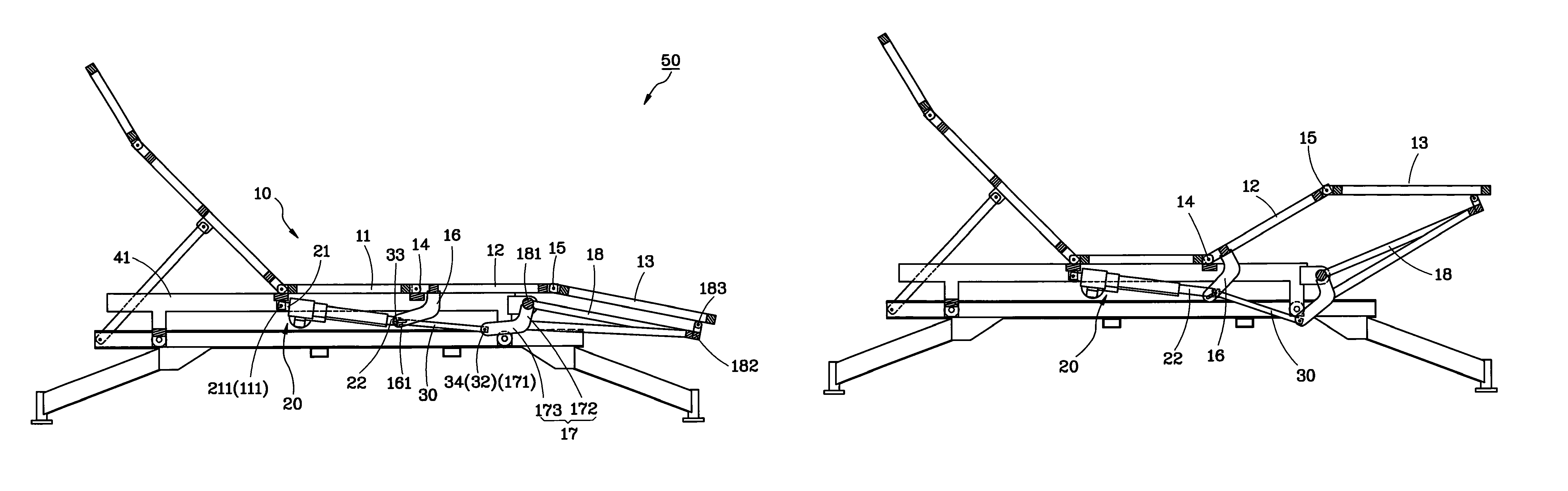
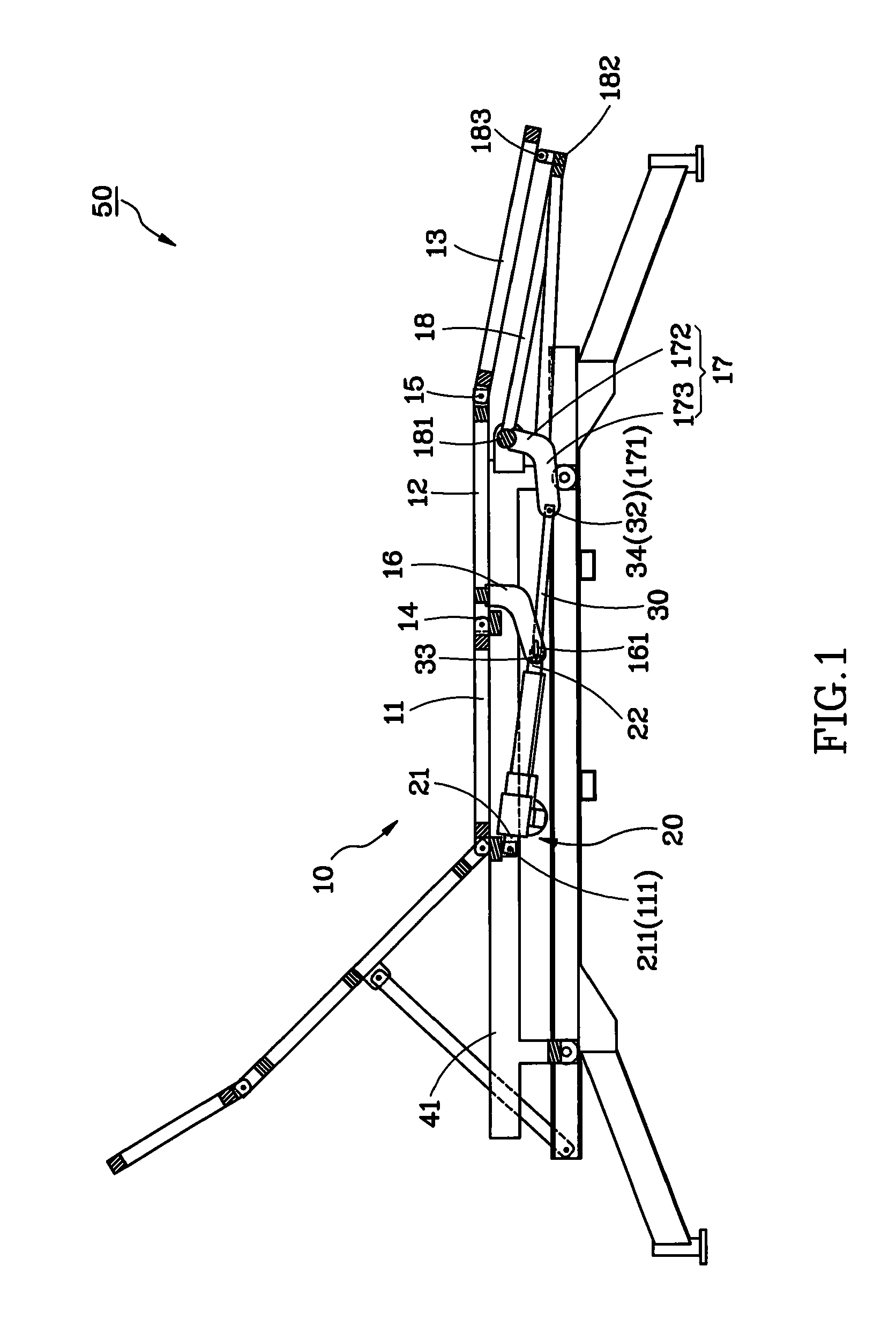
[0017]As shown in FIG. 1, a leg lift mechanism 50 for an electric bed or chair in accordance with a preferred embodiment of the present invention comprises a bed frame 41, a primary frame 10, a driver 20, and a link rod 30.

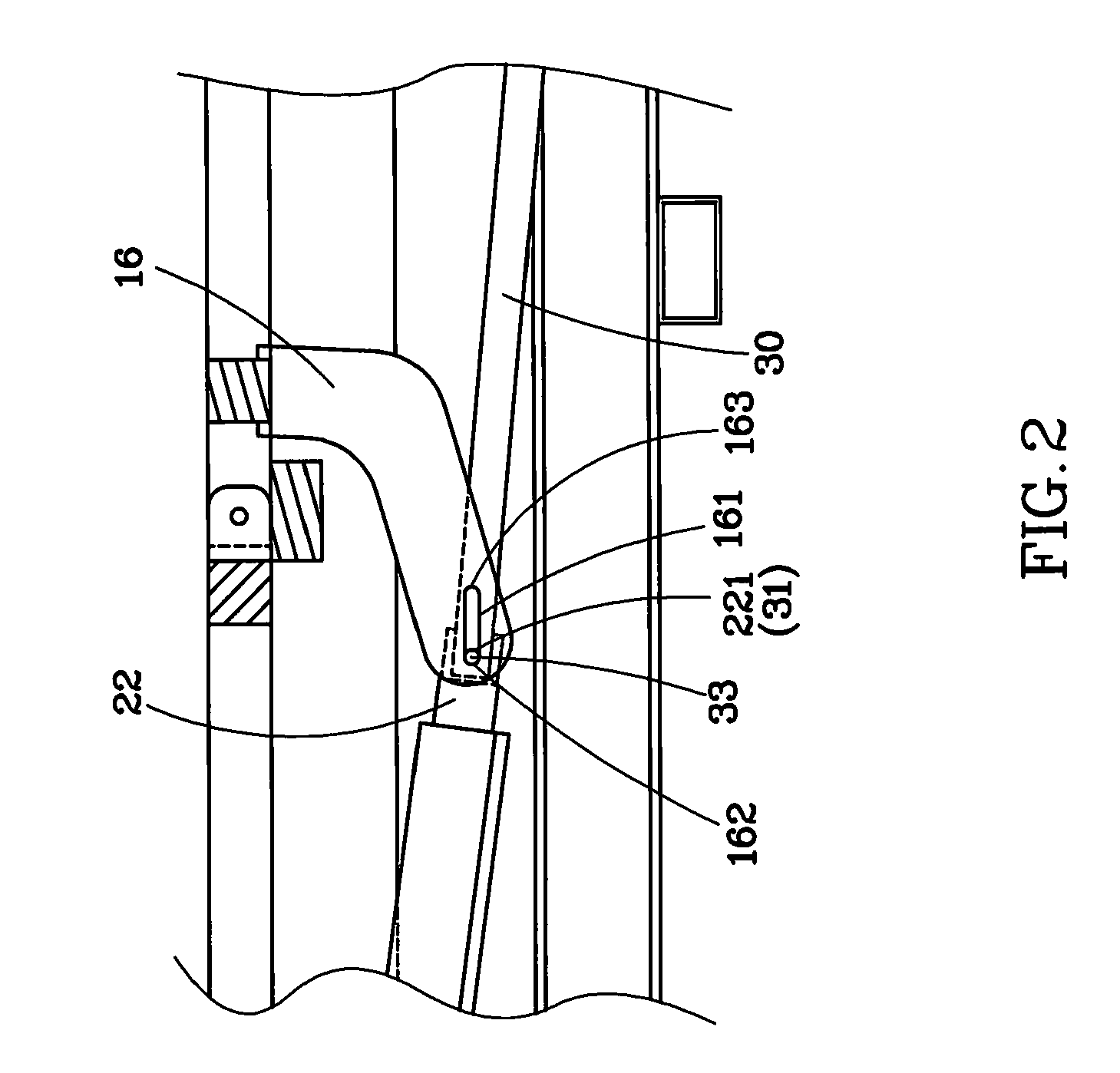
[0018]A mattress (not shown) can be placed on the primary frame 10 for allowing a user to lie down. The primary frame 10 includes a first structural component 11 mounted with the bed frame 41 and having a securing aperture 111, a second structural component 12 pivotally connected with the first structural component 11 through a first connecting element 14, and a third structural component 13 pivotally connected with the second structural component 12 through a second connecting element 15. Furthermore, two first angle brackets 16 are spacedly mounted with the second structural component 12. Each of the first angle brackets 16 is provided with a sliding slot 161, which is an elongated through hole with a front semicircular end 162 and a rear semicircular end 163, a...


PUM


Abstract

A leg lift mechanism for an electric bed or chair includes a primary frame, having a first structural component mounted with a bed frame and pivotally connected with a driver, a second structural component pivotally connected with the first structural component, a third structural component pivotally connected with the second structural component, a first angle bracket mounted with the second structural component, a lift bracket pivotally connected with the bed frame and abutted against the third structural component, and a second angle bracket mounted with the lift bracket. A link rod has an end pivotally connected with an extendable rod of the driver through a control pin inserted into a sliding slot of the first angle bracket, and the other end pivotally connected with the second angle bracket. Thus, the link rod can be driven by the driver to cause different movements of the primary frame.

Description

CROSS-REFERENCE TO RELATED APPLICATIONS[0001]This application is a Continuation-in-Part of co-pending Application No. 12 / 607,975, filed on 28 Oct. 2009, and for which priority is claimed under 35 U.S.C. §120, the entire contents of which are hereby incorporated by reference.BACKGROUND OF THE INVENTION[0002]1. Field of the Invention[0003]The present invention relates generally to an electric bed or chair, and more specifically to a leg lift mechanism for an electric bed or chair, which can perform multiple pivotal movements.[0004]2. Description of the Related Art[0005]Currently, most bed frames are designed for a user to lay flat while sleeping, and a typical bed frame includes four legs and supports. However, due to the stresses of modern life, many people suffer from insomnia and therefore suffer from a lack of sufficient rest. Consequently, many bed frames have included additional features, such as providing electrical head or leg lifting capabilities, and the user can select and ...

Claims


Application Information

Patent Timeline
Patent Type & Authority Patents(United States)
IPC IPC(8): A47B7/02
CPCA47C20/041A61G7/015
Inventor SHIH, LUNG-TAN
Owner RUOEY LUNG ENTERPRISE
Learn More