Electric motor

a technology of electric motors and motors, applied in the field of electric motors, can solve the problems of loose winding, failure of the motor, and inability to extend the winding, and achieve the effect of improving the stator

Inactive Publication Date: 2012-07-03
JOHNSON ELECTRIC SA
View PDF13 Cites 9 Cited by
  • Summary
  • Abstract
  • Description
  • Claims
  • Application Information

AI Technical Summary

Benefits of technology

[0015]Preferably, the method includes forming each interface between adjacent ends of the yokes to extend from the neck of the corresponding pole to an outer edge of the stator in a direction inclined relative to the circumferential direction of the stator.

Problems solved by technology

However, the winding is loosely wound as the force applied to the wires during winding is not sufficient to produce a tight winding in order to avoid breaking of the wires.
The loose winding cannot be arranged to extend outside of the receiving space as it is easy for turns of the winding to fall into the gap between the pole and the rotor causing failure of the motor.
However, the poles are deformed twice and the process is therefore complicated.

Method used


Image

  • Electric motor
  • Electric motor
  • Electric motor

Examples


Embodiment Construction

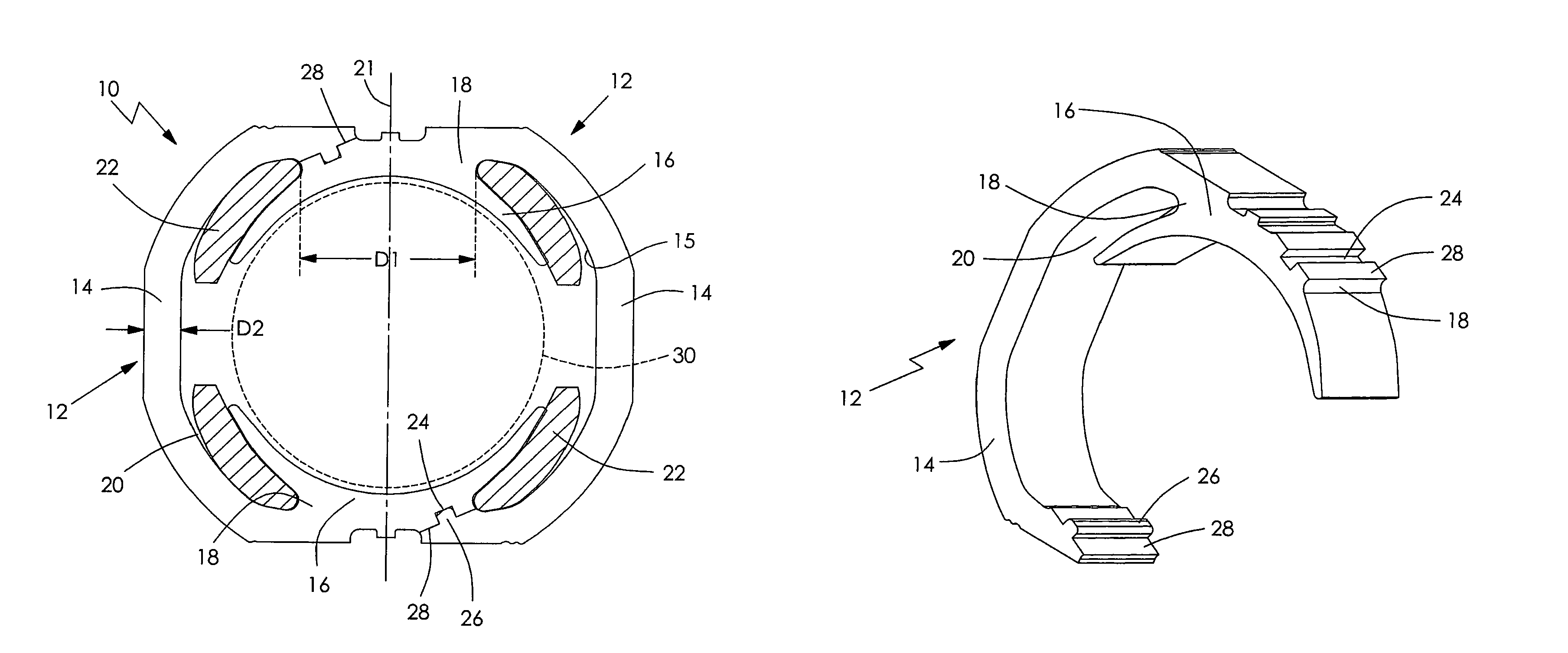
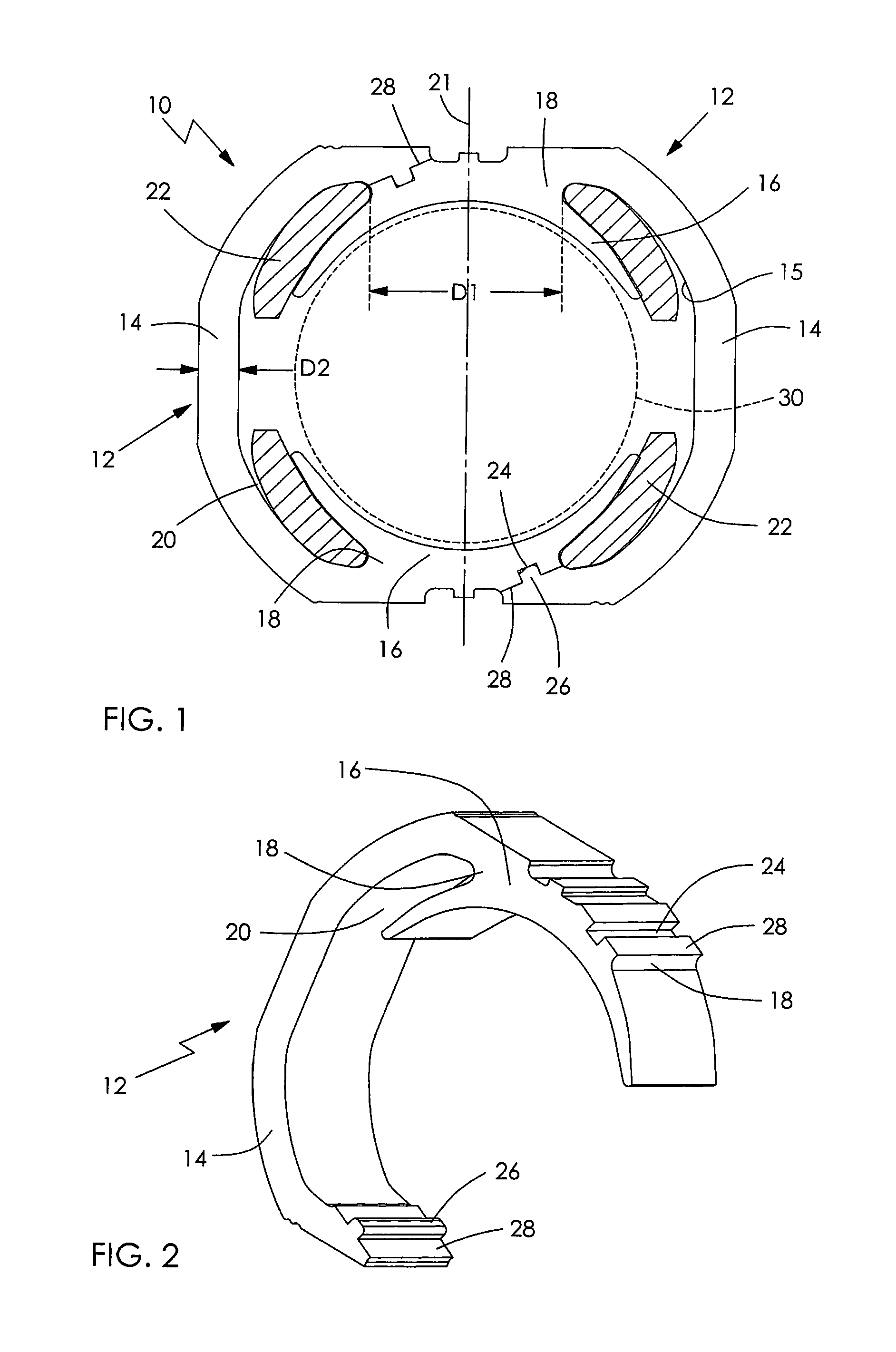
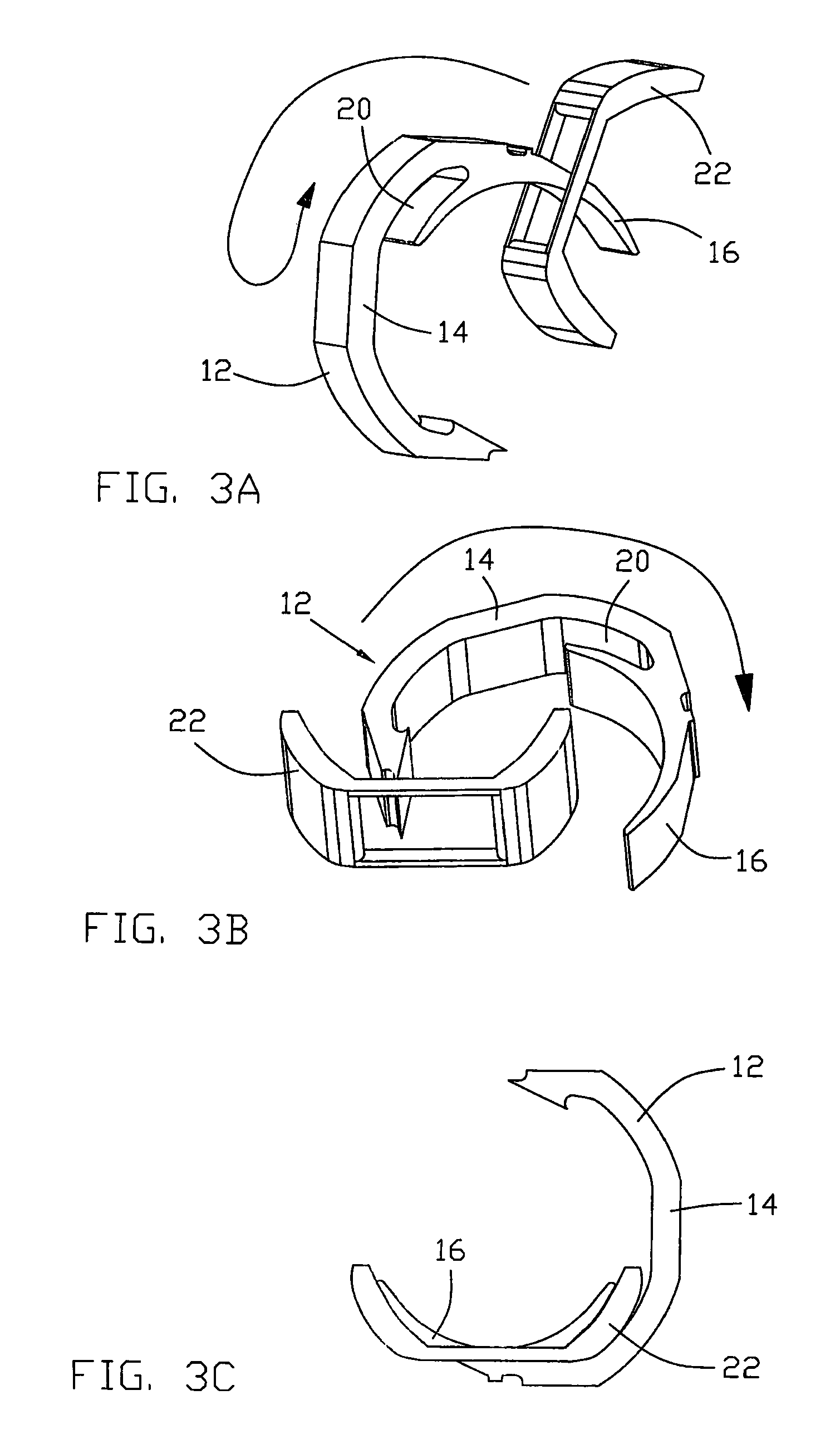
[0022]FIGS. 1 & 2 illustrate a stator for a universal motor in accordance with a preferred embodiment of the present invention. The universal motor comprises a stator 10 and a rotor 30 installed in the stator 10. The stator 10 comprises two identical stator segments 12 connected together via two interfaces there between. Each segment 12 comprises a yoke 14, a neck 18 formed at one end of the yoke 14, and a poles 16 extending from the neck 18. The pole 16 has a pole surface. The pole surfaces of both poles 16 are located on or partially form a circle surrounding the rotor. A receiving space 20 is formed between adjacent ends of the yokes 14 of the segments 12, the neck 18 and the pole 16 of one segment 12. A pre-formed winding 22 is received in each receiving space 20, surrounding the corresponding neck 18 and the poles 16. A part of the winding 22 is able to extend out of the space 20 since the winding 22 is pre-formed. Thus, the size of the winding may be increased (eg by increasin...


PUM

PropertyMeasurementUnit
lengthaaaaaaaaaa
magnetic flux densityaaaaaaaaaa
forceaaaaaaaaaa

Abstract

A universal motor has a stator and a rotor installed in the stator. The stator comprises a pair of stator segments. Each segment has a yoke with first and second ends, a pole and a neck connecting the pole to the first end of the yoke. The second end of each yoke is connected with the first end of the other yoke. A pair of pre-formed windings are mounted on respective poles of the stator segments.

Description

CROSS REFERENCE TO RELATED APPLICATIONS[0001]This non-provisional patent application claims priority under 35 U.S.C. §119(a) from Patent Application No. 20810217288.2 filed in The People's Republic of China on Nov. 7, 2008.FIELD OF THE INVENTION[0002]This invention relates to an electric motor and in particular, to a stator for a universal motor.BACKGROUND OF THE INVENTION[0003]As shown in FIG. 4, a typical stator of a universal motor consists of a plurality of single piece laminations stacked together. The stator comprises a yoke 14 and a pair of opposing poles 16 extending from an inner surface 15 of the yoke 14 via a neck 18. Receiving spaces 20 are formed between the poles 16 and the yoke 14. Windings 22 are wound around the poles 16 in the receiving spaces to locate about the neck. However, the winding is loosely wound as the force applied to the wires during winding is not sufficient to produce a tight winding in order to avoid breaking of the wires. The loose winding cannot b...

Claims


Application Information

Patent Timeline
Patent Type & Authority Patents(United States)
IPC IPC(8): H02K23/64H02K1/14H02K15/02
CPCH02K1/141H02K15/066H02K3/18Y10T29/49009
Inventor SUN, YAO QILI, YONGGUI, LI PING
Owner JOHNSON ELECTRIC SA
Why Eureka
Try Eureka