Remote monitoring system and method controlling the same

a monitoring system and remote control technology, applied in the field of monitoring systems, can solve the problems of user inability to be informed, remote control is not performed, and it takes a relatively longer time to perform one process, so as to achieve the effect of convenient user interaction and prevent unnecessary power consumption

Active Publication Date: 2012-07-10
LG ELECTRONICS INC
View PDF26 Cites 6 Cited by
  • Summary
  • Abstract
  • Description
  • Claims
  • Application Information

AI Technical Summary

Benefits of technology

[0045]As described above, the remote monitoring system and the method controlling the same has following industrial advantageous effects.
[0046]First, unnecessary power consumption can be prevented, because power is selectively applied to the displayer of the remote monitoring unit by means of judging if the power cord of a device selected by a user is connected.
[0047]Second, the user can recognize conditions of power cord connection of a device he / she has selected.
[0048]Third, in case the power cord of a device is on again, it can be identified if the device is operated or not.
[0049]Fourth, in case a user selects a device sensed to be power-off, the device to be monitored can be automatically changed into the other device put into operation.
[0050]Fifth, it is more convenient to a user, because monitoring is selectively possible without additional key input parts, even though power-off is sensed.

Problems solved by technology

Especially, there have been under development application to home appliances such as washer and dryers, which takes relatively longer time to perform one process.
However, considering that a conventional washer has a function automatically shutting off power when predetermined time passes while not performing any cycles, it can be said that remote controlling is not performed when the power of the washing machine is off.
In case of performing remote controlling and monitoring through the internet, there are some problems that a PC capable of monitoring should be on and that a home network should be built.
Furthermore, in case that a washer and a dryer are installed in a distant place such as a outside storehouse and a basement laundry room, there are difficulties in creating the network place and also there are inconveniences that the user should frequently visit the place to check out the devices after he / she carries the laundry to the distant place to load the laundry and input an operation instruction.
Still further, since errors during the operation cannot be noticed, the user cannot be informed that the operations such as a washing cycle or a drying cycle is stopped due to the errors, only to maintain that state.
Still further, since it is possible to input an instruction of an operation only in the distant place having a washer and a dryer, an inconvenience may be caused to the user.

Method used


Image

  • Remote monitoring system and method controlling the same
  • Remote monitoring system and method controlling the same
  • Remote monitoring system and method controlling the same

Examples


first embodiment

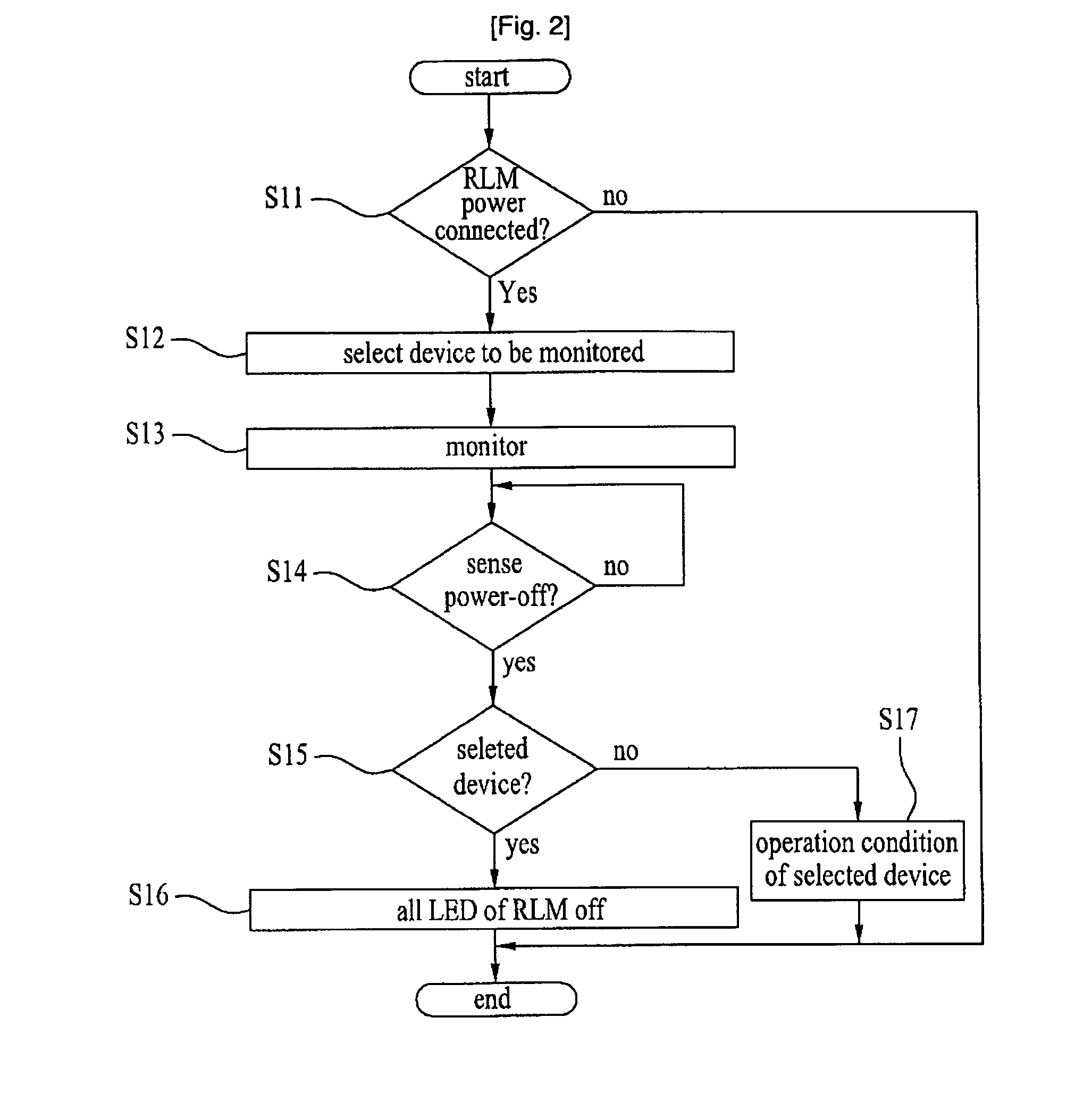
[0080]FIG. 5 is a flow chart illustrating a method controlling the remote monitoring system according to the present invention.

[0081]The method controlling the remote monitoring system according to the first embodiment of the present invention is that a monitored device is selected or a display window of a device is off based on conditions of power cord connection.

[0082]First of all, it is judged if the power is connected to a RLM (S501).

[0083]Next, according to the result, once the power is connected to the RLM, a device the user wants to remote monitor is selected (S502).

[0084]Hence, the selected device is monitored (S503).

[0085]At that time, it is judged if data is inputted from the selected device for a predetermined period of time (S504).

[0086]According to the result, once there is no inputted data for the predetermined period of time, a message for demanding to identify a condition of the selected device is transmitted to the device by the remote monitoring unit (S505).

[0087]H...

second embodiment

[0095]A method controlling the remote monitoring system according to present invention is that a monitored device is selected based on conditions of power switches and monitoring is controlled in case the selected device is a dryer.

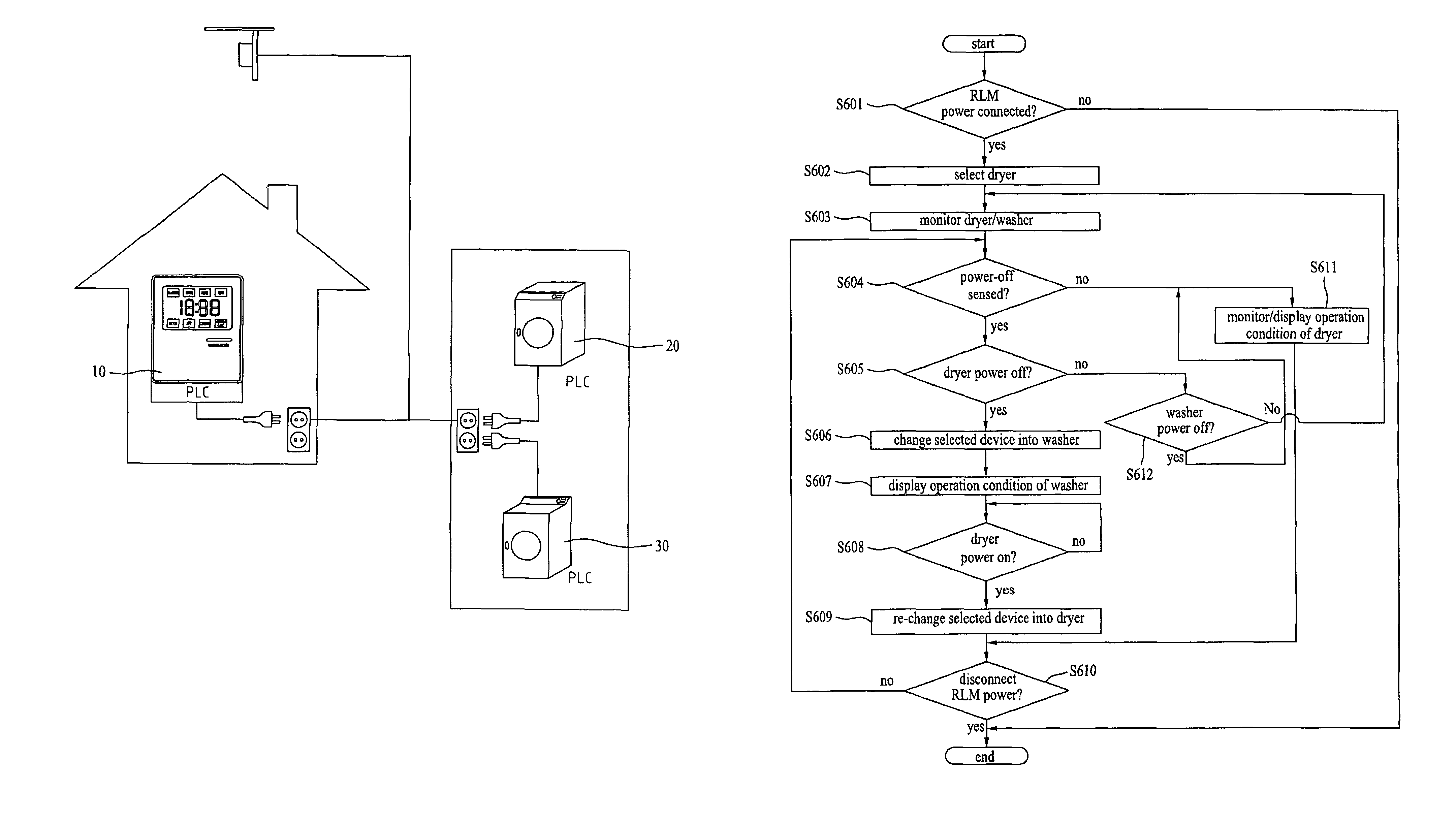
[0096]FIG. 6 is a flow chart illustrating the second embodiment of the method controlling the remote monitoring system.

[0097]First, it is judged if power is connected to a RLM (S601).

[0098]Next, once the power is connected to the RLM based on the result of the step (S601), a user selects a dryer (S602).

[0099]Hence, the selected dryer is monitored (S603).

[0100]It is judged if the power of the dryer is off, together with monitoring the selected dryer (S604) (S605).

[0101]If the power of the dryer is on, that means the user selects to monitor the dryer. Thereby, the dryer is monitored normally (S611).

[0102]If the dryer is judged to be off, a device selected to be monitored is changed into a washer (S606).

[0103]Hence, an operation condition of the washing mach...

third embodiment

[0109]On the other hand, a method controlling the remote monitoring system according to the present invention is that a monitored device is selected based on conditions of power switches, for a case that the selected device is a washer.

[0110]FIG. 7 is a flow chart illustrating a third embodiment of a method controlling the remote monitoring system according to the present invention.

[0111]First, it is judged if power is connected to a remote monitoring system (S701).

[0112]Once the power is judged to be connected to the remote monitoring system by the result, it means that a user selects a washer (S702).

[0113]Hence, the selected washer is monitored (S703).

[0114]It is judged if the power of the washer is off, with monitoring the selected washer (S704) (S705).

[0115]If the washer is power-on, it means the user selects to monitor the washer, so that the washer is monitored (S711).

[0116]Whereas, if the washer is judged power-off, a device selected to be remote monitored is changed into a d...


PUM


Abstract

The present invention relates to a remote monitoring system and a method controlling the same, which can selectively monitor according to a condition of power and a control of devices including a washer and a dryer installed in a remote place. The remote monitoring system comprises a communication module provided in each device for transmitting monitoring information after identifying an operation condition of each device according to a user's demand; and a remote monitoring unit for selecting a device to be monitored based on a result after identifying a power condition of each device, as well as displaying an operation condition of each device based on the transmitted monitoring information and the control of each device.

Description

[0001]This application claims priority to PCT / KR2006 / 000250, filed Jan. 23, 2006, published on Aug. 3, 2006, Publication No. WO 2006 / 080792 A1 in the English language and claims priority to Korean Application Nos. 10-2005-0006625, filed Jan. 25, 2005 and 10-2005-0022950, filed Mar. 19, 2005. The entire disclosure of the prior applications is considered as being part of the disclosure of the accompanying application and is hereby incorporated by reference therein.TECHNICAL FIELD[0002]The present invention relates to a monitoring system, and more particularly, to a remote monitoring system and a method controlling the same, which can selectively monitor according to a condition of power and a control of devices including a washer and a dryer installed in a remote place.BACKGROUND ART[0003]In general, a washer is an appliance which performs washing through a washing, rinsing, and spinning cycle, once a user introduces dirty laundry into a tub and then detergent and washing water are mi...

Claims


Application Information

Patent Timeline
Patent Type & Authority Patents(United States)
IPC IPC(8): G05B23/02
CPCD06F33/02D06F39/005D06F58/28D06F2210/00D06F2101/20D06F34/32D06F2103/68D06F58/36D06F2105/58D06F33/32D06F34/05
Inventor KWON, YONG HOANCHOI, KYOO CHEOLLEE, HOON BONGKIM, YONG TAE
Owner LG ELECTRONICS INC
Why Eureka
Try Eureka