
Electronic equipment and power supply state control method for electronic equipment

a power supply state control and electronic equipment technology, applied in the field of electronic equipment and power supply state control methods for electronic equipment, can solve the problems of long time taken until, many existing cec-compatible equipments take a relatively long time to start a cec facility, and many users perform power supply turning-on manipulations. the effect of reducing the time elapsed until the power supply is actually turned on

Inactive Publication Date: 2010-02-11
SONY CORP
View PDF6 Cites 26 Cited by
  • Summary
  • Abstract
  • Description
  • Claims
  • Application Information

AI Technical Summary

Benefits of technology

[0010]Thus, it is desirable to shorten the time to be taken until a power supply is actually turned on after a user performs a power supply turning-on manipulation.
[0018]The electronic equipment in accordance with the embodiment of the present invention has as a power supply state an off state, a standby state, and an on state. The off state is a state into which when a power supply turning-off manipulation is performed, the power supply of the electronic equipment is finally changed. The on state is a state into which when a power supply turning-on manipulation is performed, the power supply is finally changed. When the power supply turning-on manipulation is performed with the power supply state set to the off state, the electronic equipment initiates system start. When the system start is completed, the power supply state is finally set to the on state. The standby state is a state in an intermediate stage between the off state and on state, and is a state that takes a shorter time for being changed to the on state than for being changed to the off state.
[0020]As mentioned above, when the power supply turned-on information on an external equipment is acquired, the power supply state is changed in advance from the off state to the standby state. Therefore, when the power supply turning-on manipulation is performed, the standby state is merely changed to the on state. The time elapsing until the power supply is actually turned on after a user performs the power supply turning-on manipulation can be shortened.
[0021]The electronic equipment of the embodiment of the present invention may further include an information-on-power supply turning-off manipulation acquisition unit that acquires information on a power supply turning-off manipulation. When the information on the power supply turning-off manipulation is acquired by the information-on-power supply turning-off manipulation acquisition unit with the power supply state set to the on state, the power supply state control unit may change the power supply state from the on state to the standby state. In this case, for example, assuming that the power supply turning-off manipulation is performed on the external equipment by mistake and the power supply turning-on manipulation is immediately performed on the external equipment, the standby state is merely changed to the on state. Therefore, the time elapsing until the power supply is actually turned on after a user performs the power supply turning-on manipulation can be shortened.
[0022]Now, for example, after the power supply state is changed into the standby state, although a predetermined time has elapsed, if the information-on-manipulation acquisition unit does not acquire the information on the power supply turning-on manipulation, the power supply state is changed from the standby state to the off state. When the power supply turning-off manipulation performed on the external equipment is no mistake, the power supply turning-on manipulation will not be immediately performed on the external equipment. In this case, the power supply can be prevented from being retained in the standby state. Eventually, unnecessary power consumption can be prevented.
[0023]According to the embodiment of the present invention, the power supply state is controlled so that: when the power supply turned-on information concerning the external equipment connected over the transmission line is acquired with the power supply state set to the off state, the off state will be changed to the standby state; and when the information on the power supply turning-on manipulation is acquired with the power supply state set to the standby state, the standby state will be changed to the on state. The time elapsing until the power supply is actually turned on after a user performs the power supply turning-on manipulation can be shortened.

Problems solved by technology

Many existing CEC-compatible equipments take a relatively long time to start a CEC facility.
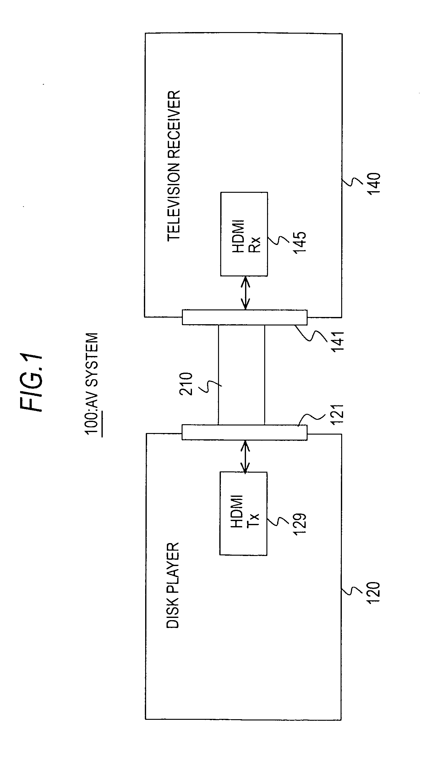
Therefore, for example, in an AV system including a television receiver and a DVD player that are connected to each other over an HDMI cable, a long time is taken until the power supply of the DVD player is actually turned on after a user performs a power supply turning-on manipulation on a television receiver.
This poses a problem in that it takes considerable time until an image and sounds reproduced by the DVD player are outputted from the television receiver.

Method used


Image

  • Electronic equipment and power supply state control method for electronic equipment
  • Electronic equipment and power supply state control method for electronic equipment
  • Electronic equipment and power supply state control method for electronic equipment

Examples


concrete example 1

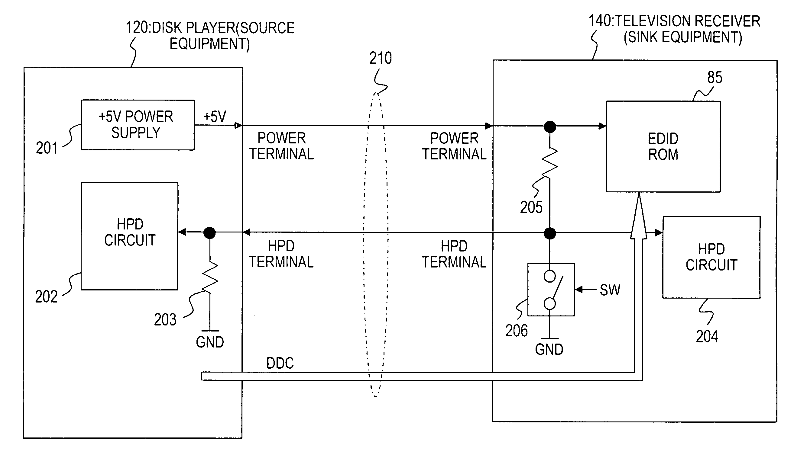
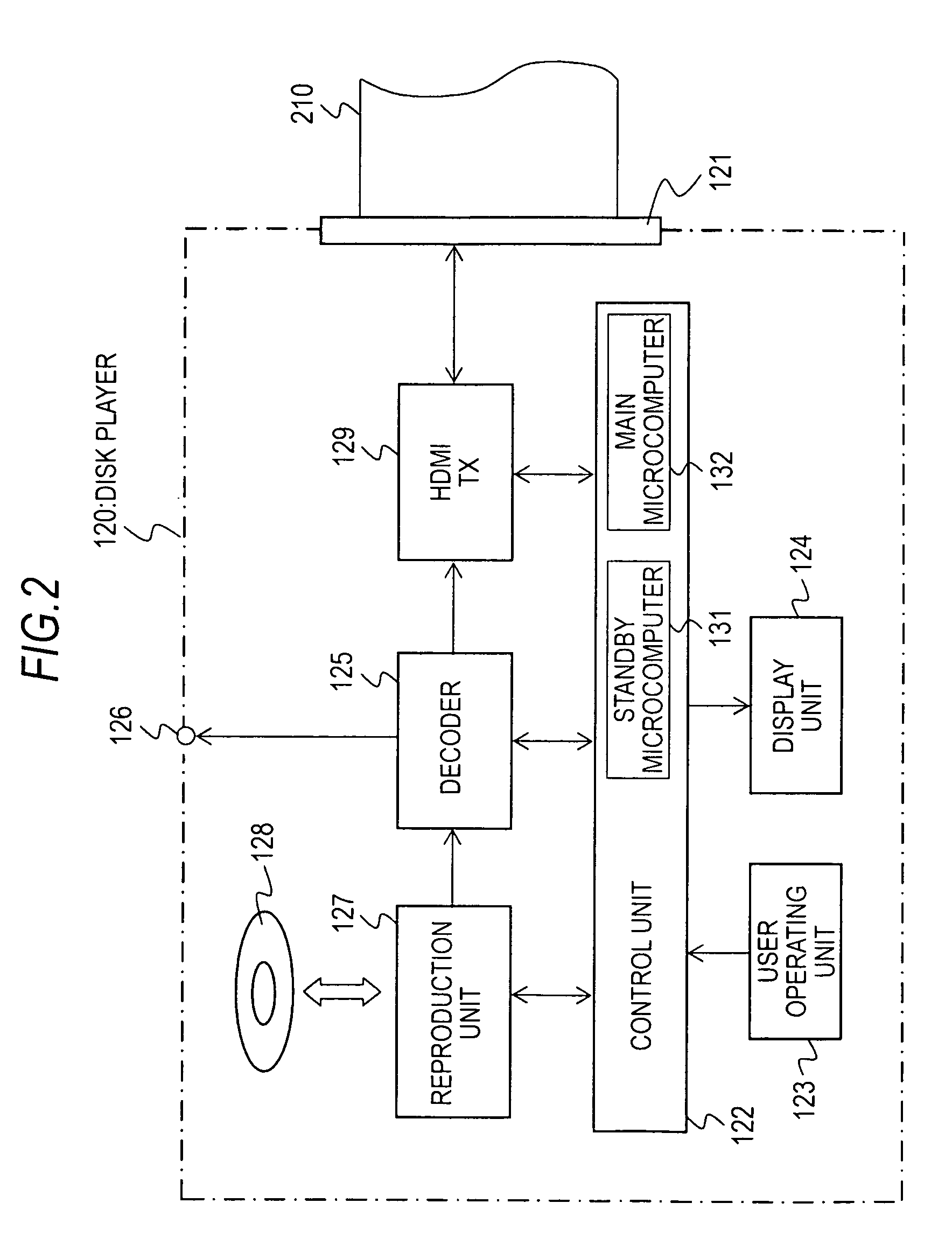
[0136]A concrete example 1 will be described below. In the concrete example 1, a description will be made of a case where: the power supply interlocking facility employing the CEC line in the HDMI cable is energized in the television receiver 140; both the disk player 120 and television receiver 140 have the power supplies thereof turned off; and a user performs a manipulation of turning on the power supply of the television receiver 140. Incidentally, the main power supplies (ACON) of the disk player 120 and television receiver 140 alike shall be on.

[0137]To begin with, referring to FIG. 15, an example of a control action in accordance with a related art will be described. (a) When a user performs the manipulation of turning on the power supply of the television receiver 140, the television receiver 140 initiates system start. In a time T1, the television receiver 140 completes the system start. The power supply state is set to the on state.

[0138](b) After the power supply state is...

concrete example 2

[0149]A concrete example 2 will be described below. In the concrete example 2, a description will be made of a case where: the power supply interlocking facility employing the CEC line in the HDMI cable is energized in the television receiver 140; the power supplies of both the disk player 120 and television receiver 140 are turned on; and a user performs a manipulation of turning off the power supply of the television receiver 140.

[0150]To begin with, referring to FIG. 17, an example of a control action to be performed when a user performs the manipulation of turning off the power supply of the television receiver 140 will be described below.

[0151](a) When a user performs the manipulation of turning off the power supply of the television receiver 140, the television receiver 140 has the power supply thereof turned off. (b) After the power supply state is set to the off state, the television receiver 140 transmits Power Off as User Control Pressed information, which corresponds to p...

concrete example 3

[0161]A concrete example 3 will be described below. In the concrete example 3, a description will be made of a case where: the power supply interlocking facility employing the CEC line in the HDMI cable is de-energized in the television receiver 140; the power supplies of both the disk player 120 and television receiver 140 are turned off; a user performs a manipulation of turning on the power supply of the television receiver 140 so as to start the system of the television receiver 140; and the user then performs an input switching manipulation on the disk player 120, and performs the manipulation of turning on the power supply of the disk player 120.

[0162]To begin with, referring to FIG. 19, an example of a control action in accordance with the related art will be described below. (a) When a user performs the manipulation of turning on the power supply of the television receiver 140, the television receiver 140 initiates system start. In a time T1, the television receiver 140 comp...


PUM


Abstract

An electronic equipment includes:a data transmission unit that transmits or receives content data to or from an external equipment;a power supply turned-on information acquisition unit that acquires power supply turned-on information concerning the external equipment;an information-on-manipulation acquisition unit that acquires information on a power supply turning-on manipulation; anda power supply state control unit that controls a power supply state into any of an off state, a standby state, and an on state,wherein when the power supply turned-on information concerning the external equipment with the power supply state set to the off state is acquired, the power supply state control unit changes the power supply state to the standby state; andwhen the information on the power supply turning-on manipulation with the power supply state set to the standby state is acquired, the power supply state control unit changes the power supply state to the on state.

Description

CROSS-REFERENCE TO RELATED APPLICATION[0001]The present application claims priority from Japanese Patent Application No. JP 2008-206255 filed in the Japanese Patent Office on Aug. 8, 2008, the entire content of which is incorporated herein by reference.BACKGROUND OF THE INVENTION[0002]1. Field of the Invention[0003]The present invention relates to an electronic equipment and a power supply state control method for an electronic equipment. More particularly, the present invention is concerned with an electronic equipment and a power supply state control method for an electronic equipment that make it possible to shorten the time, which elapses until a power supply is actually turned on after a user performs a power supply turning-on manipulation, by controlling a power supply state so that: when power supply turned-on information on an external equipment connected over a transmission line is acquired with the power supply state set to an off state, the power supply state will be chan...

Claims


Application Information

Patent Timeline
Patent Type & Authority Applications(United States)
IPC IPC(8): H02J1/00H04N7/173H04N21/436H04N21/442H04Q9/00H04Q9/04
CPCG09G5/006G09G2330/021G09G2370/12H04N5/765H04N21/4436H04N7/163H04N21/42646H04N21/43622H04N21/44231H04N5/85
Inventor GOTO, HIROTAKAUCHIUMI, YUKO
Owner SONY CORP
Learn More