Single direct current arc chamber, and bi-directional direct current electrical switching apparatus employing the same

a direct current arc chamber and single-arc chamber technology, applied in the direction of air-break switches, high-tension/heavy-dress switches, electrical equipment, etc., can solve the problems of unidirectional operation of dc electrical switching apparatus, difficulty in implementing a permanent magnet design for a typical dc mccb without a significant increase in size and cos

Active Publication Date: 2012-07-17
EATON INTELLIGENT POWER LTD
View PDF13 Cites 60 Cited by
  • Summary
  • Abstract
  • Description
  • Claims
  • Application Information

AI Technical Summary

Problems solved by technology

Known molded case circuit breakers (MCCBs) are not specifically designed for use in direct current (DC) applications.
One of the challenges in DC current interruption / switching, especially at a relatively low DC current, is to drive the arc into the arc interruption chamber.
Known problems associated with such permanent magnets in known DC electrical switching apparatus include unidirectional operation of the DC electrical switching apparatus, and two separate arc chambers each including a plurality of arc plates and a set of contacts must be employed to provide bi-directional operation.
These problems make it very difficult to implement a permanent magnet design for a typical DC MCCB without a significant increase in size and cost.

Method used


Image

  • Single direct current arc chamber, and bi-directional direct current electrical switching apparatus employing the same
  • Single direct current arc chamber, and bi-directional direct current electrical switching apparatus employing the same
  • Single direct current arc chamber, and bi-directional direct current electrical switching apparatus employing the same

Examples


example 1

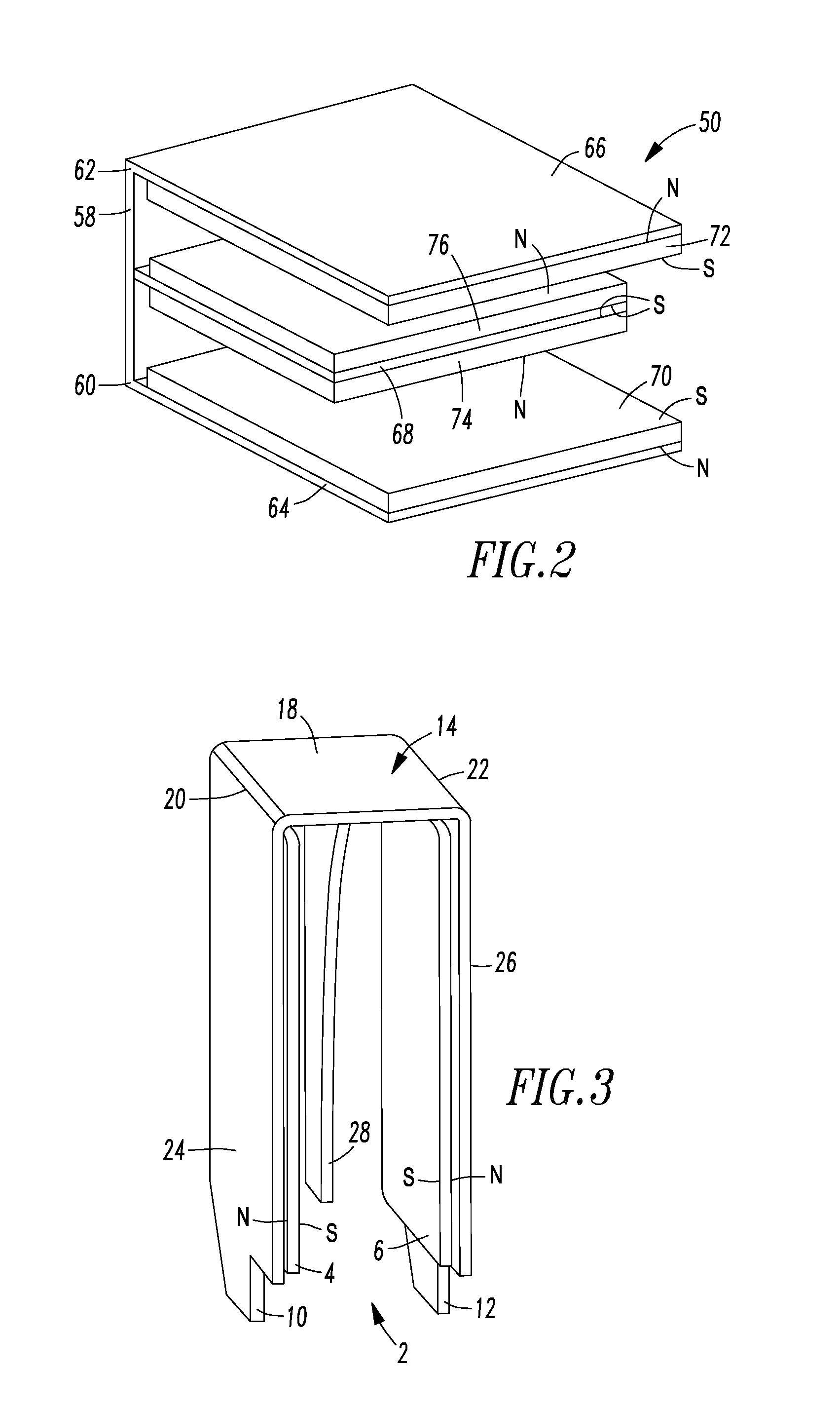
[0033]Also referring to FIGS. 7 and 8, the first end 20 of the ferromagnetic base 18 and the first ferromagnetic side member 24 disposed from the first end 20 define a first corner 30, and the opposite second end 22 of the ferromagnetic base 18 and the second ferromagnetic side member 26 disposed from the opposite second end 22 define a second corner 32. The single direct current arc chamber 8 defines a magnetic field pattern 34. A movable contact arm 38 carries a movable contact 40, which electrically engages a fixed contact 42 carried by a stationary conductor 44. Whenever an arc 46 is struck between the movable contact 40 and the fixed contact 42, which are disposed between the first and second ferromagnetic side members 24,26, the magnetic field pattern 34 is structured to drive the arc toward one of the first and second corners 30,32 depending on a direction of current flowing in the arc 46. For example, for current flowing from the movable contact 40 to the fixed contact 42, t...

example 2

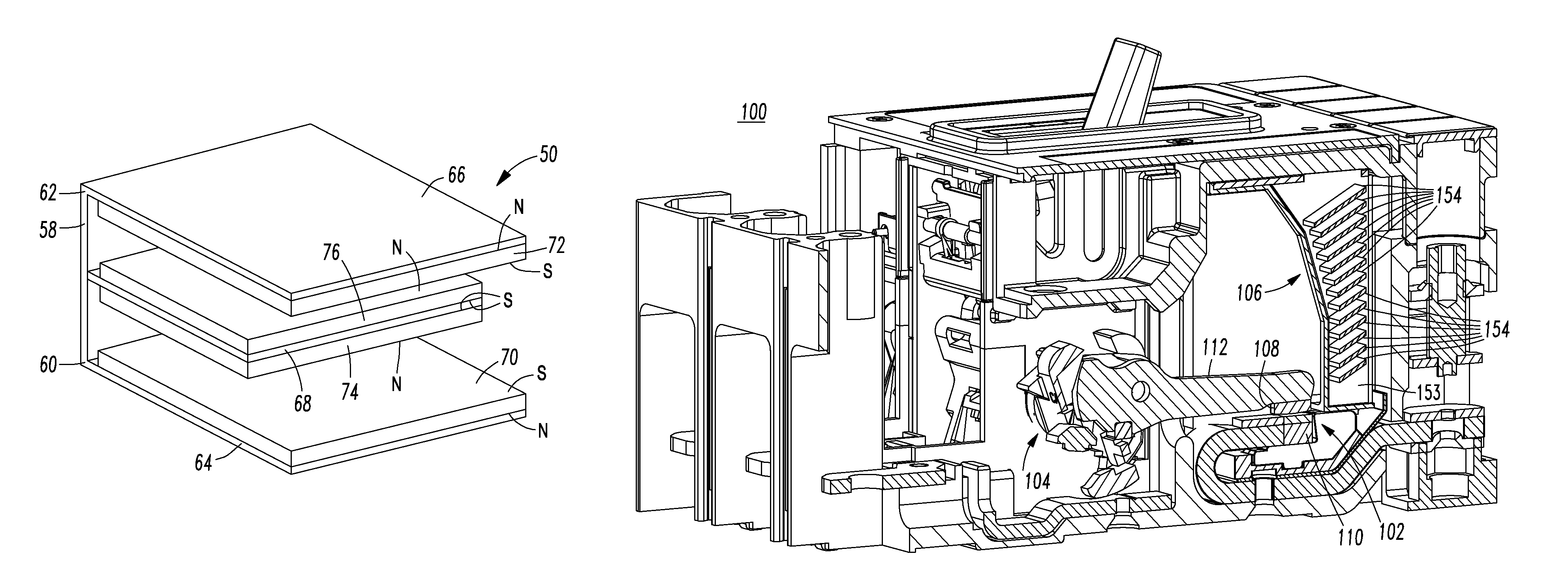
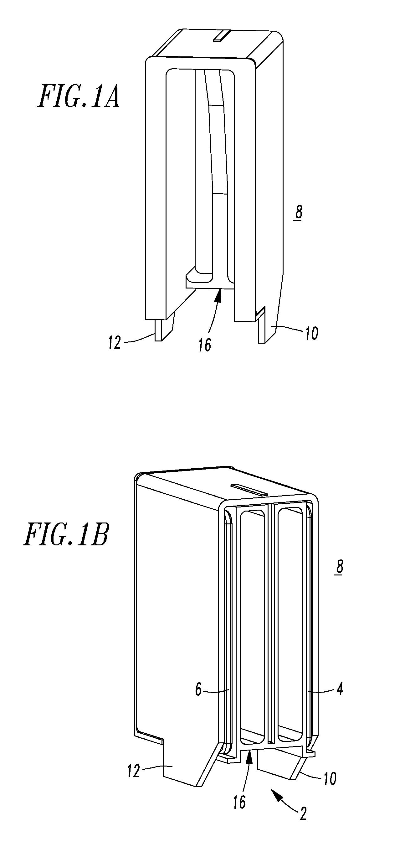
[0035]Referring to FIG. 2, another single direct current arc chamber 50 includes a ferromagnetic base 58 having a first end 60 and an opposite second end 62, a first ferromagnetic side member 64 disposed from the first end 60, a second ferromagnetic side member 66 disposed from the opposite second end 62, and a third ferromagnetic member 68 disposed from the ferromagnetic base 58 intermediate the first and second ferromagnetic side members 64,66. A first permanent magnet 70 has a first magnetic polarity (S), is disposed on the first ferromagnetic side member 64 and faces the third ferromagnetic member 68. A second permanent magnet 72 has the first magnetic polarity (S), is disposed on the second ferromagnetic side member 66 and faces the third ferromagnetic member 68. A third permanent magnet 74 has an opposite second magnetic polarity (N), is disposed on the third ferromagnetic member 68 and faces the first permanent magnet 70 having the first magnetic polarity (S). A fourth perman...

example 3

[0037]FIG. 5 (closed position) and FIG. 6 (open position) show a bi-directional, direct current electrical switching apparatus 100 including separable contacts 102, an operating mechanism 104 structured to open and close the separable contacts 102, and a single direct current arc chamber 106, which may be the same as or similar to the single direct current arc chamber 8 (FIG. 1B) or the single direct current arc chamber 50 (FIG. 2). FIG. 6 shows the separable contacts 102 (shown in phantom line drawing in a partially open position, which corresponds to the partially open position in FIG. 7).

[0038]The separable contacts 102 include a movable contact 108 and a fixed contact 110. The operating mechanism 104 includes a movable contact arm 112 carrying the movable contact 108 with respect to the single direct current arc chamber 106.


PUM


Abstract

A single direct current arc chamber includes a ferromagnetic base having first and opposite second ends, a first ferromagnetic side member disposed from the first end, a second ferromagnetic side member disposed from the opposite second end, a third ferromagnetic member disposed from the ferromagnetic base intermediate the ferromagnetic side members, a first permanent magnet having a first magnetic polarity disposed on the first ferromagnetic side member and facing the third ferromagnetic member, and a second permanent magnet having the first magnetic polarity disposed on the second ferromagnetic side member and facing the third ferromagnetic member.

Description

BACKGROUND[0001]1. Field[0002]The disclosed concept pertains generally to electrical switching apparatus and, more particularly, to direct current electrical switching apparatus, such as, for example, direct current circuit breakers. The disclosed concept further pertains to direct current arc chambers.[0003]2. Background Information[0004]Electrical switching apparatus employing separable contacts exposed to air can be structured to open a power circuit carrying appreciable current. These electrical switching apparatus, such as, for instance, circuit breakers, typically experience arcing as the contacts separate and commonly incorporate arc chambers, such as arc chutes, to help extinguish the arc. Such arc chutes typically comprise a plurality of electrically conductive plates held in spaced relation around the separable contacts by an electrically insulative housing. The arc transfers to the arc plates where it is stretched and cooled until extinguished.[0005]Known molded case circ...

Claims


Application Information

Patent Timeline
Patent Type & Authority Patents(United States)
IPC IPC(8): H01H9/30
CPCH01H9/34H01H9/443
Inventor ZHOU, XINJUDS, MARK A.KODELA, NARESH K.BEATTY, JR., WILLIAM E.
Owner EATON INTELLIGENT POWER LTD
Why Eureka
Try Eureka