Impact detector and packaging container

a detector and packaging technology, applied in the direction of force sensors, instruments, force/torque/work measurement apparatuses, etc., can solve the problems of fragile packaged articles such as precision apparatuses falling or falling due to careless handling, and affecting the quality of the produ

Active Publication Date: 2012-08-07
RICOH KK
View PDF30 Cites 29 Cited by
  • Summary
  • Abstract
  • Description
  • Claims
  • Application Information

AI Technical Summary

Problems solved by technology

In the course of transport, it sometimes happen that fragile packaged articles such as precision apparatuses fall or drop due to careless handling, accidents, or the like.
The impact of the fall or drop can damage the articles.
However, although falling of the packaged article can be detected in both the anteroposterior direction and the lateral direction, this configuration has several drawbacks.
For example, this configuration makes the impact detector relatively bulky because a path through which the weight moves from the initial position to the impact detection position is formed for each of impact to a back side and impact to a front side.
In addition, because a single inspection window is used to detect both anteroposterior impact and lateral impact, users cannot identify the direction in which the packaged article has fallen because this configuration does not distinguish between anteroposterior impact and lateral impact, that is, for example, between the back side and a right side and between the front side and a left side.

Method used


Image

  • Impact detector and packaging container
  • Impact detector and packaging container
  • Impact detector and packaging container

Examples


second embodiment

[0063]An impact detector 200 is described below.

[0064]FIG. 6A is a cross-sectional view from a front side illustrating the impact detector 200. FIG. 6B illustrates a cross section of the impact detector 200 along a line B-B shown in FIG. 6A.

[0065]The impact detector 200 includes a lid 201 and a case body 210 to which the lid 201 is attached. The lid 201 and the case body 210 together form a case. As shown in FIG. 6B, the impact detector 200 includes a lid-side transition path 215a, serving as a first transition path, formed on the side of the lid 201 and a case-side transition path 215b, serving as a second transition path, formed on the side of the case body 210. The lid-side-transition path 215a and the case-side transition path 215b are adjacent to each other in a direction perpendicular to the surface of paper on which FIG. 6A is drawn. In FIG. 6B, the lid-side-transition path 215a and the case-side transition path 215b communicate with each other in a lower portion and are sep...

third embodiment

[0074]An impact detector is described below.

[0075]FIG. 7A is a cross-sectional view from a front side illustrating an impact detector 300 according the third embodiment, and FIG. 7B illustrates a lid of the impact detector shown in FIG. 7A.

[0076]The impact detector 300 according to the present embodiment includes an anteroposterior impact detector 310 to indicate impact history in an anteroposterior direction and an impact detector 320 to indicate impact history in a lateral direction as well as drop history, that is, history of impact from below in FIG. 7A. The anteroposterior impact detector 310 is attached to an upper portion of the impact detector 320.

first embodiment

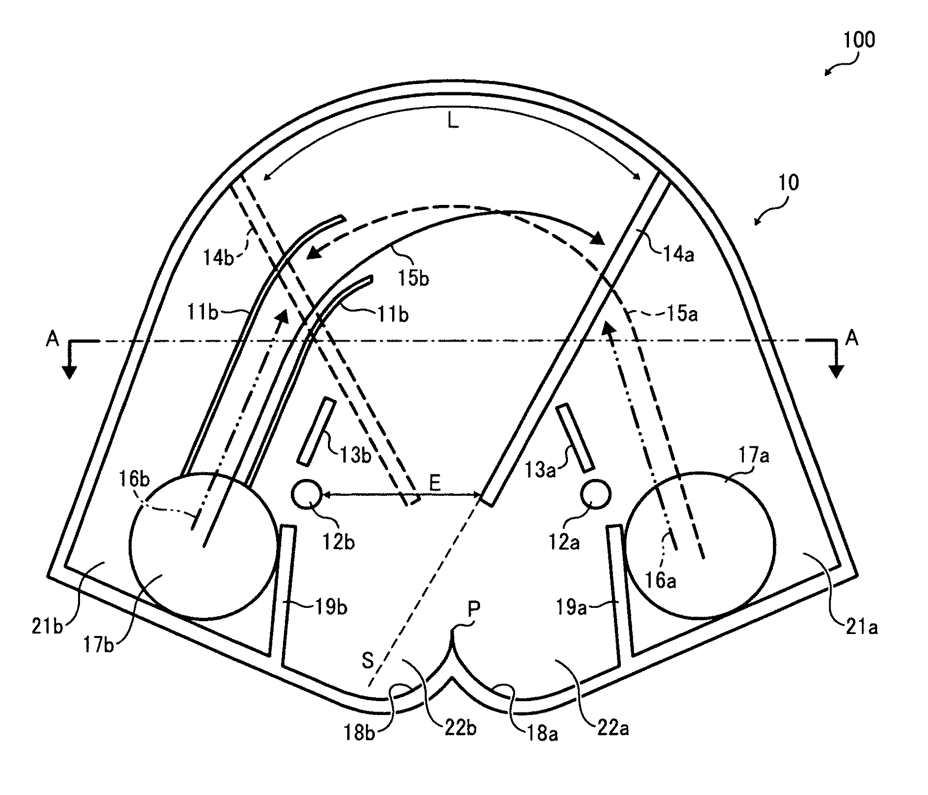
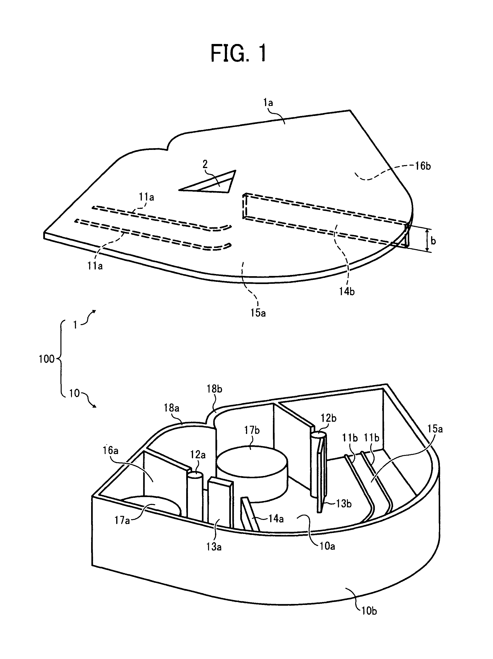
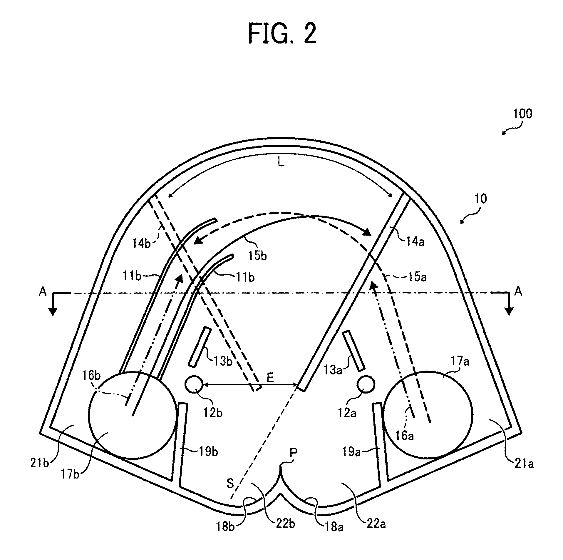
[0077]The anteroposterior impact detector 310 has a configuration similar to that of the impact detector 100 shown in FIGS. 1 through 5B and components identical or similar to those of the impact detector 100 are given identical reference characters. Thus, descriptions of the anteroposterior impact detector 310 are omitted. With the configuration, the impact history in the four different directions, that is, to the front side, the back side, the right side, and the left side can be indicated with a single weight, and thus the impact detector can be relatively simple.

[0078]The impact detector 320 can indicate how may times the impact detector 300 has been dropped, that is, has received impact from below, up to twice and impact history of the impact detector 300 in the lateral direction (lateral falling history), that is, whether or not the impact detector 300 has tilted laterally to a certain degree. Case bodies of the impact detector 320 and the anteroposterior impact detector 310 ...


PUM

PropertyMeasurementUnit
weightsaaaaaaaaaa
weightaaaaaaaaaa
weight movementaaaaaaaaaa

Abstract

An impact detector includes a case, an impact indicator disposed on a front side of the case, to indicate an impact history of the impact detector, a first weight that moves inside the case to a side to which the case falls, causing the impact indicator to indicate the impact history by moving through at least one of a first transition path and a second transition path, a first guide member to guide the first weight to a first impact detection position along the first transition path when the case falls in a first direction, and a second guide member to guide the first weight to the second impact detection position along the second transition path when the case falls in a second direction. The first transition path at least partly overlaps with the second transition path on a projection plane on the front side of the case.

Description

CROSS-REFERENCE TO RELATED APPLICATIONS[0001]This patent specification is based on and claims priority from Japanese Patent Application Nos. 2009-126117, filed on May 26, 2009, and 2010-015107 filed on Jan. 27, 2010 in the Japan Patent Office, the contents of which are hereby incorporated by reference herein in its entirety.BACKGROUND OF THE INVENTION[0002]1. Field of the Invention[0003]The present invention generally relates to an impact detector to detect impact to an article and a packaging container including the impact detector.[0004]2. Discussion of the Background Art[0005]In the course of transport, it sometimes happen that fragile packaged articles such as precision apparatuses fall or drop due to careless handling, accidents, or the like. The impact of the fall or drop can damage the articles. For this reason, therefore, impact detectors are typically attached to packaged articles to detect whether or not the article has been subjected to impact.[0006]For example, impact de...

Claims


Application Information

Patent Timeline
Patent Type & Authority Patents(United States)
IPC IPC(8): G01L5/00G01N3/30
CPCG01L5/008
Inventor NARUISHI, MOKUISHIKAWA, SAKAEARAI, TOMOAKI
Owner RICOH KK
Why Eureka
Try Eureka