High-pressure pump

a high-pressure pump and pump body technology, applied in the direction of pump components, positive-displacement liquid engines, pulse equalisation, etc., can solve the problem of well-restricted fuel pressure pulsation

Active Publication Date: 2012-09-11
DENSO CORP
View PDF6 Cites 4 Cited by
  • Summary
  • Abstract
  • Description
  • Claims
  • Application Information

AI Technical Summary

Benefits of technology

[0008]The present invention is made in view of the above matters, and it is an object of the present invention to provide a high-pressure pump which is capable of restricting a fuel pressure pulsation even when a flow velocity of a fuel returning to a fuel gallery is increased.

Problems solved by technology

Consequently, even when the flow velocity of the fuel returned to the fuel gallery is increased, the fuel pressure pulsation can be well restricted.

Method used


Image

  • High-pressure pump
  • High-pressure pump
  • High-pressure pump

Examples


Embodiment Construction

[0014]Hereafter, an embodiment of the present invention will be described. A high-pressure pump is mounted to a vehicle for pumping up fuel in a fuel tank through a fuel inlet and pressurizes the fuel. The high-pressure pump supplies the pressurized fuel to a fuel rail to which an injector is connected. The fuel inlet of the high-pressure pump is fluidly connected to a low-pressure pump (not shown) through a pipe.

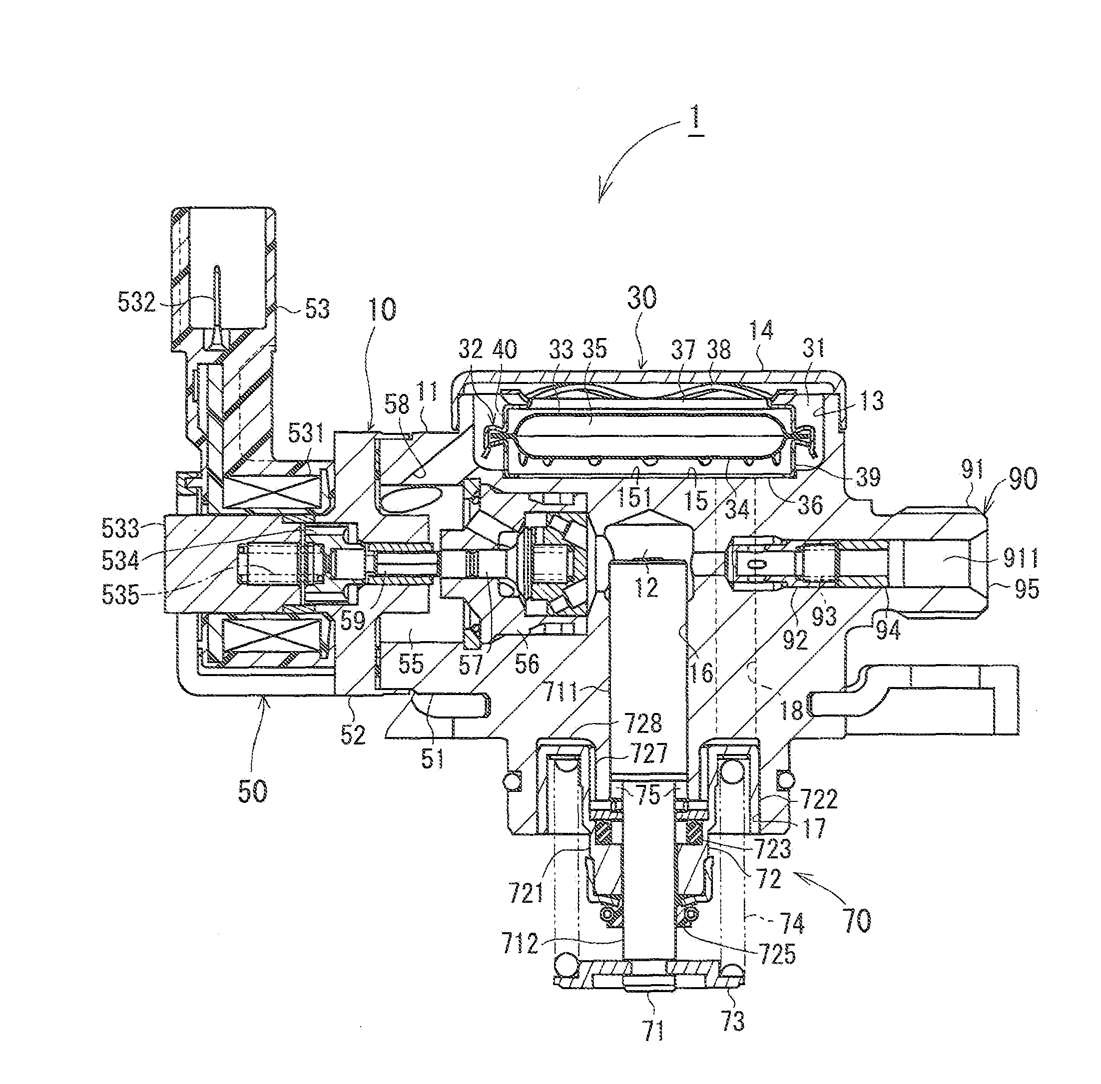
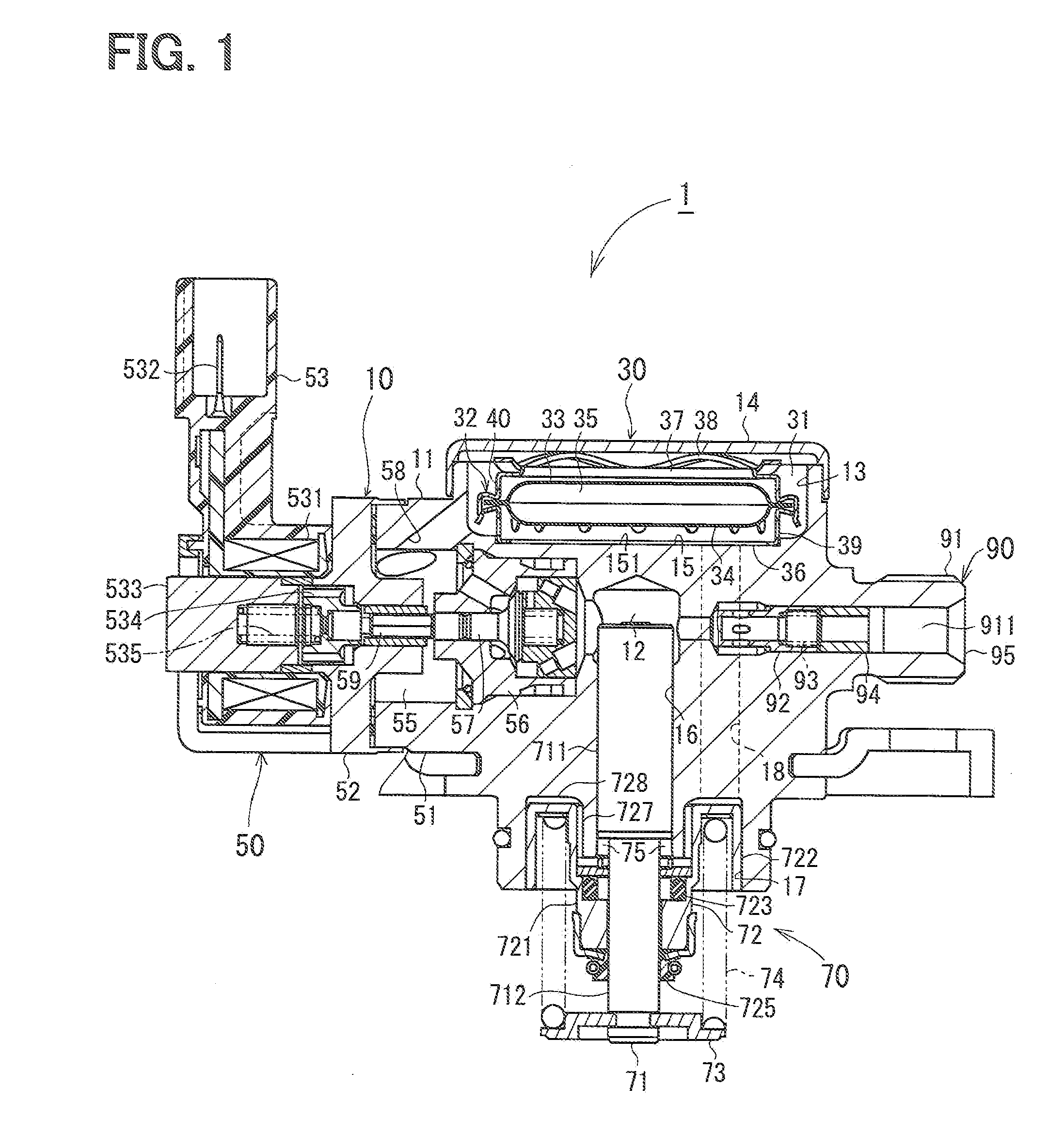
[0015]As shown in FIG. 1, a high-pressure pump 1 is comprised of a main body 10, a fuel supply portion 30, a suction valve portion 50, a plunger portion 70, and a discharge valve portion 90.

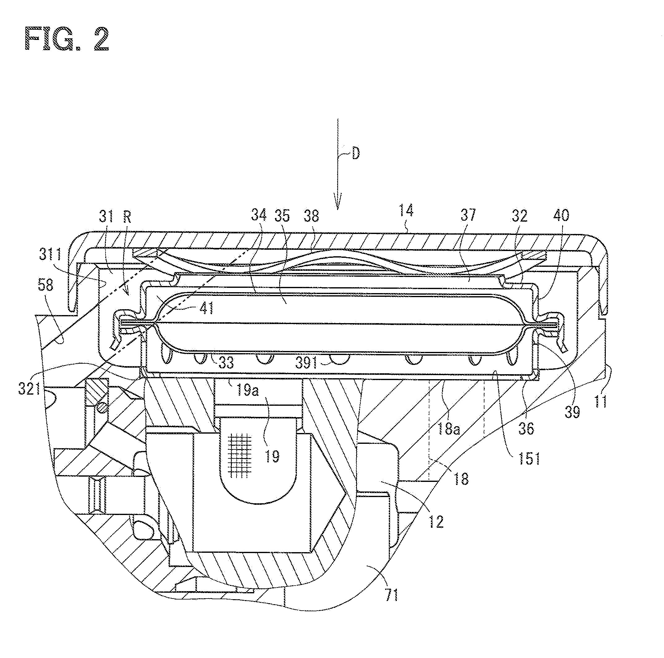
[0016]The main body 10 includes a housing 11 which forms an outer profile of the high-pressure pump 1. The fuel supply portion 30 is formed on the housing 11. The plunger portion 70 is formed at an opposite side of the fuel supply portion 30. A compression chamber 12 is defined in the housing 11 between the plunger portion 70 and the fuel supply portion 30. The suction valve portion 50 a...


PUM


Abstract

An extended passage of a press-side passage is supposed in a fuel gallery. This supposed extended passage of the press-side passage extends toward a lid member. The press-side passage is opened at the side wall of the fuel gallery. A center axis of the press-side passage is inclined in such a manner that a fuel returning from the press-side passage to the fuel gallery flows toward the lid member. A bottom-side fringe of a damper unit does not exist in the supposed extended passage.

Description

CROSS-REFERENCE TO RELATED APPLICATION[0001]This application is based on Japanese Patent Application No. 2009-256384 filed on Nov. 9, 2009, the disclosure of which is incorporated herein by reference.FIELD OF THE INVENTION[0002]The present invention relates to a high-pressure pump used for an internal combustion engine.BACKGROUND OF THE INVENTION[0003]The high-pressure pump is generally provided with a plunger which reciprocates along with a camshaft of an engine. Specifically, when the plunger slides down from its top dead center to its bottom dead center, a fuel in a fuel gallery is suctioned into a compression chamber (suction stroke). When the plunger slides up from the bottom dead center to the top dead center, a part of the low-pressure fuel is returned to the fuel gallery (metering stroke). Then, after a suction valve is closed, when the plunger further slides up, the fuel in the compression chamber is compressed (compression stroke).[0004]As an engine speed becomes high and ...

Claims


Application Information

Patent Timeline
Patent Type & Authority Patents(United States)
IPC IPC(8): F04B11/00
CPCF04B11/0033
Inventor INOUE, HIROSHI
Owner DENSO CORP
Why Eureka
Try Eureka