Vehicle door opening angle control system

a control system and vehicle door technology, applied in the direction of process and machine control, wing accessories, instruments, etc., can solve the problems of increasing the total system cost to a large extent, affecting the operation of the system, and the area of one ultrasonic sensor being insufficient relative to the size of the vehicle door

Active Publication Date: 2012-10-02
DENSO CORP
View PDF9 Cites 17 Cited by
  • Summary
  • Abstract
  • Description
  • Claims
  • Application Information

AI Technical Summary

Benefits of technology

[0009]It is therefore an object of the present invention to provide a vehicle door opening angle control system, which is capable of detecting an obstacle even in a case that a sufficient amount of laser light cannot be received from the obstacle because of shallow incidence angle of the laser light to the obstacle and a low loser light reflectivity of the obstacle.

Problems solved by technology

In case of detecting the distance from the vehicle door to the obstacle by generating an ultrasonic wave pulse in a direction perpendicular to the outer surface of the vehicle door from the ultrasonic sensor provided on the vehicle door and receiving the ultrasonic wave pulse reflected by the obstacle, the area, which one ultrasonic sensor can cover in detecting an obstacle, is not sufficient relative to the size of the vehicle door.
However, such a number of sensors necessarily increase total system costs to a large extent.
As a result, it becomes impossible to detect the other vehicle (distance thereto), which is an obstacle, although the other vehicle actually is present.
Further, a similar situation, in which a sufficient amount of reflected laser light cannot be received from an obstacle, will arise, if a reflective body is in black or similar color and its reflectivity of the laser light is low.

Method used


Image

  • Vehicle door opening angle control system
  • Vehicle door opening angle control system
  • Vehicle door opening angle control system

Examples


first embodiment

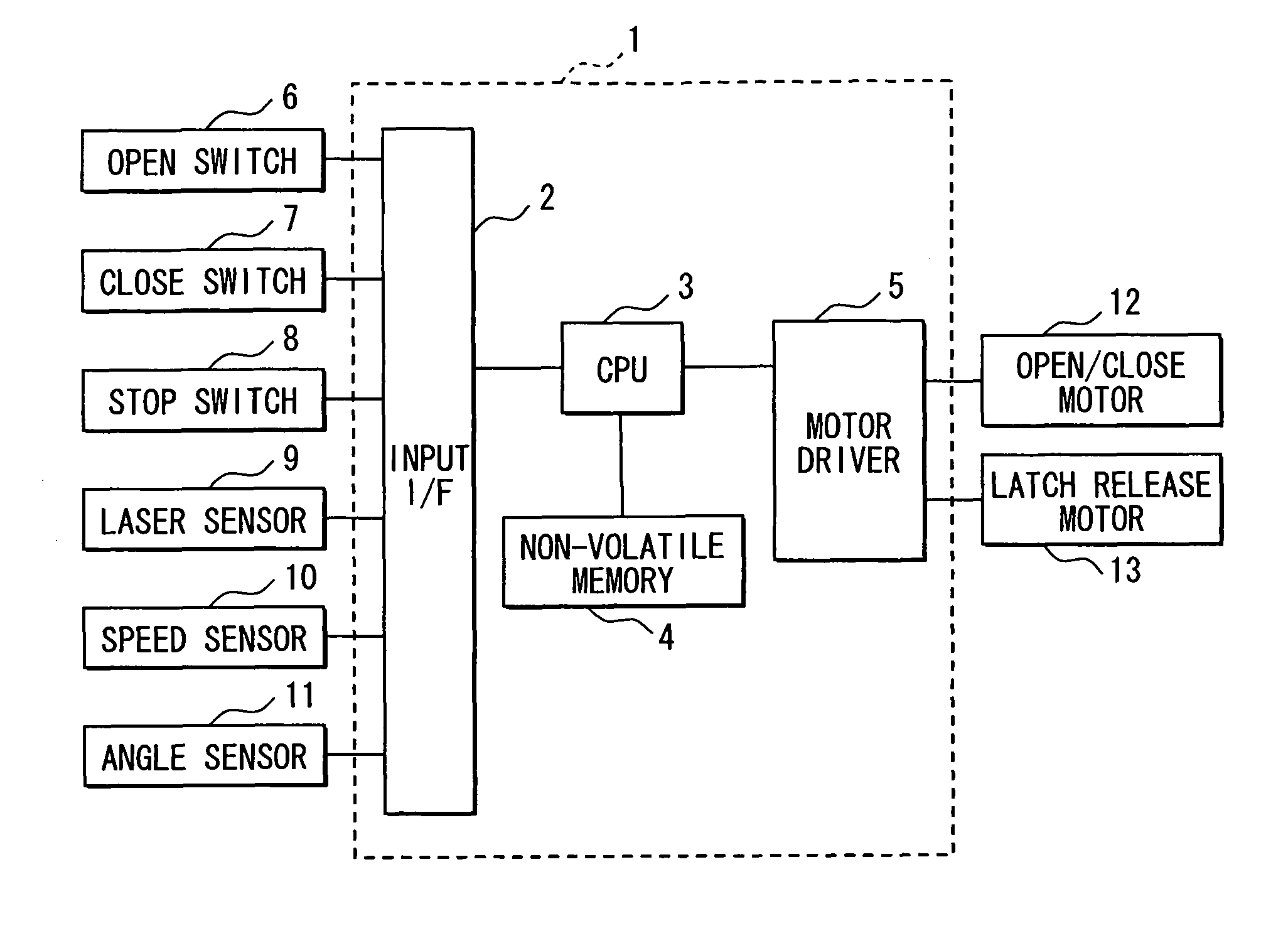
[0029]Referring to FIG. 1, a vehicle door opening angle control system is principally configured with an electronic control unit (ECU) 1 for executing various control processing, various switches 6 to 8 and sensors 9 to 11, an open / close motor 12 for opening and closing a vehicle door and a latch release motor 13. With this configuration, the vehicle door is automatically opened and closed by the use of two kinds of motors upon user's switch manipulation.

[0030]The vehicle door opening angle control system shown in FIG. 1 is configured to automatically open and close one vehicle door. However, it may be provided for only any one of vehicle doors such as a driver's seat-side door, for both the driver's seat-side door and a front passenger's seat-side door or for all vehicle doors of the vehicle. If the vehicle door opening angle control system according to this embodiment is applied to a plurality of vehicle doors, the same system is provided for each of the vehicle doors.

[0031]The va...

second embodiment

[0082]The vehicle door opening angle control system according to the second embodiment of the present invention will be described next. This door opening angle control system is configured to have the same configuration as that of the first embodiment. In the first embodiment, it is assumed that a sufficient amount of laser light cannot be received, because the obstacle is present near the subject vehicle and the laser light is incident to the obstacle shallowly. With this assumption, it is determined that the obstacle is present, if the reflected laser light cannot be received even when the laser light is projected downward from the laser sensor 9.

[0083]However, if the obstacle is present near the vehicle as shown in FIG. 15B and the obstacle has a certain level of a mirror reflectivity and a low level of refractive reflectivity against the laser light, the laser sensor 9 will possibly receive the laser light reflected by the ground by way of the obstacle. That is, if the laser lig...

third embodiment

[0093]The vehicle door opening angle control system according to the third embodiment of the present invention will be described next. This door opening angle control system is also configured to have the same configuration as that of the first embodiment.

[0094]In the second embodiment, it is differentiated by adjusting the intensity of the laser light outputted from the laser sensor 9 whether the laser light has been reflected directly by the ground or indirectly by the ground by way of the obstacle. According to this embodiment, it is differentiated based on changes over time in the intensity of the received laser light whether the laser light has been directly reflected or indirectly reflected by way of the obstacle.

[0095]The method of differentiating whether the received laser light results from the direct reflection at the ground or the indirect reflection by way of the obstacle is described with reference to FIG. 16.

[0096]This obstacle detection processing is the same as that ...


PUM


Abstract

A laser sensor projects laser light in the downward direction. If the laser sensor does not receive any laser light reflected by an obstacle or the ground, it is determined that the obstacle is present in the direction of projection of the laser light. It is thus possible to detect the presence of the obstacle, which will at least affect the opening of the vehicle door.

Description

CROSS REFERENCE TO RELATED APPLICATION[0001]This application is based on and incorporates herein by reference Japanese Patent Applications No. 2009-49776 filed on Mar. 3, 2009 and No. 2010-034856 filed on Feb. 19, 2010.FIELD OF THE INVENTION[0002]The present invention relates to a vehicle door opening angle control system, which controls the opening angle of a vehicle door not to touch an obstacle.BACKGROUND OF THE INVENTION[0003]It is conventional, as disclosed in JP-U-2-132515 for example, to provide an ultrasonic sensor on a vehicle door and detect a distance from the ultrasonic sensor to an obstacle so that the vehicle door may be prevented from touching the obstacle when it is opened.[0004]In case of detecting the distance from the vehicle door to the obstacle by generating an ultrasonic wave pulse in a direction perpendicular to the outer surface of the vehicle door from the ultrasonic sensor provided on the vehicle door and receiving the ultrasonic wave pulse reflected by the...

Claims


Application Information

Patent Timeline
Patent Type & Authority Patents(United States)
IPC IPC(8): B60R22/00
CPCE05F15/43E05Y2900/531E05F2015/483E05F2015/434
Inventor NAKAKURA, YOHEIKONISHI, TOSHIYUKIHIOKI, HIDEKIOKADA, YOSHIHISA
Owner DENSO CORP
Why Eureka
Try Eureka