Anti-reflective integrated touch display panel

a touch display panel and integrated technology, applied in non-linear optics, instruments, optics, etc., can solve the problems of reducing the display quality of the display panel, increasing the manufacturing cost of the display device accordingly, and reducing the shift of the neutral axis, so as to enhance the flexibility of the anti-reflective integrated touch display panel, reduce the interference from noise, and reduce the effect of shifting the neutral axis

Active Publication Date: 2020-02-20
AU OPTRONICS CORP
View PDF0 Cites 6 Cited by
  • Summary
  • Abstract
  • Description
  • Claims
  • Application Information

AI Technical Summary

Benefits of technology

[0016]One of the purposes of the disclosure is to reduce the shift of the neutral axis of the anti-reflective integrated touch display panel.
[0017]One of the purposes of the disclosure is to enhance the flexibility of the anti-reflective integrated touch display panel.
[0018]One of the purposes of the disclosure is to reduce the interference from the noise on the anti-reflective integrated touch display pane

Problems solved by technology

However, the cost of circular polarizers is expensive and the manufacturing cost of display dev

Method used


Image

  • Anti-reflective integrated touch display panel
  • Anti-reflective integrated touch display panel
  • Anti-reflective integrated touch display panel

Examples


Embodiment Construction

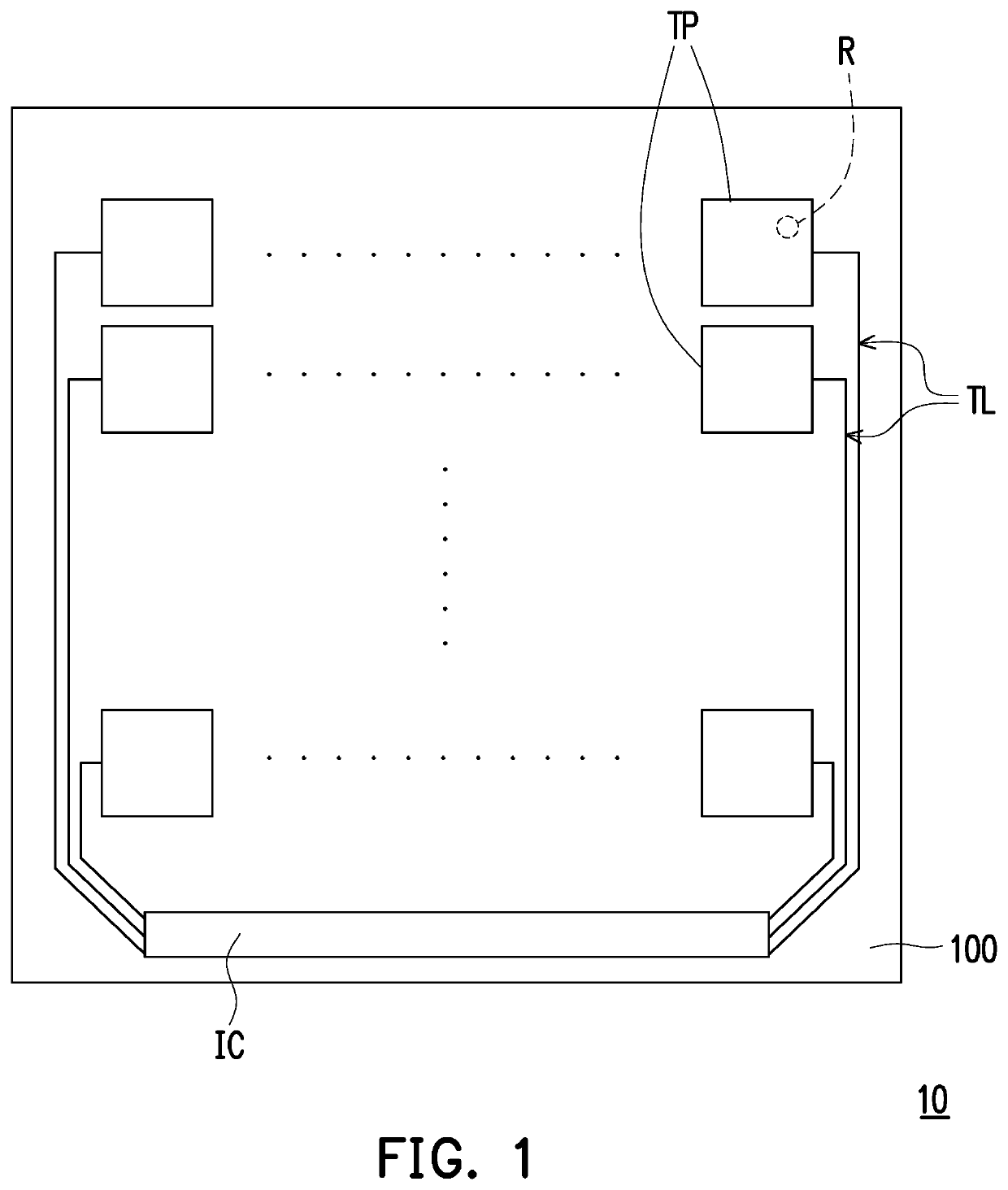
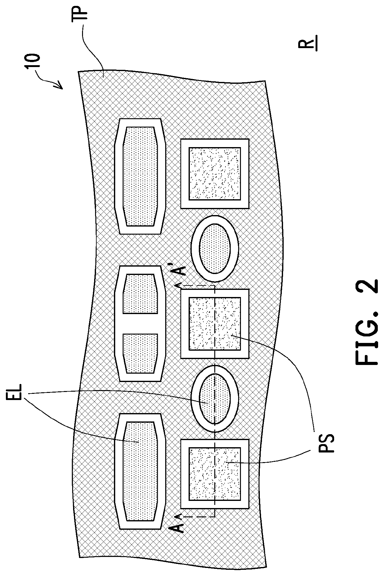
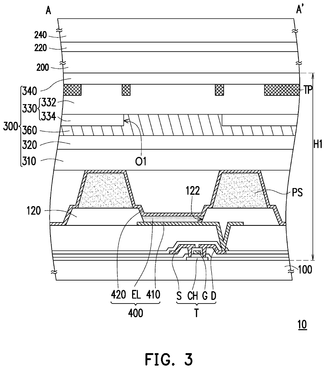
[0030]FIG. 1 is a top schematic diagram of an anti-reflective integrated touch display panel according to the first embodiment of this disclosure. For easier illustration and observation, some elements are omitted in FIG. 1. FIG. 2 is a partially enlarged top schematic diagram of a region R in the anti-reflective integrated touch display panel of FIG. 1. For easier illustration and observation, some elements are omitted in FIG. 2. FIG. 3 is a cross-sectional schematic view of the anti-reflective integrated touch display panel of FIG. 2 along a section line AA′. Please refer to FIG. 1, FIG. 2, and FIG. 3. In the first embodiment of this disclosure, an anti-reflective integrated touch display panel 10 includes an anti-reflective structure 300 and a plurality of touch electrodes TP. In this embodiment, the anti-reflective integrated touch display panel 10 includes a first substrate 100, an anti-reflective structure 300, the touch electrodes TP, a second substrate 200, a protective laye...


PUM


Abstract

An anti-reflective integrated touch display panel includes an anti-reflective structure and touch electrodes. The anti-reflective structure includes a first insulating layer, a second insulating layer disposed on the first insulating layer, a conducting layer disposed on the second insulating layer, a third insulating layer disposed on the second insulating layer, and a fourth insulating layer disposed on the third insulating layer. The first insulating layer includes silicon oxide or silicon nitride, and has a thickness of 0.1 to 2 micrometers. The second insulating layer includes silicon oxide or strontium oxide, and has a thickness of 0.001 to 0.1 micrometer. The conducting layer includes molybdenum, and has a thickness of 0.01 to 0.05 micrometer. The fourth insulating layer includes silicon nitride, and has a thickness of 0.001 to 0.3 micrometer. The touch electrodes are disposed between the third insulating layer and the fourth insulating layer.

Description

CROSS REFERENCE TO RELATED APPLICATION[0001]This application claims the priority benefit of Taiwan application serial no. 107128385, filed on Aug. 14, 2018. The entirety of the above-mentioned patent application is hereby incorporated by reference herein and made a part of specification.BACKGROUND OF THE DISCLOSUREField of the Disclosure[0002]The disclosure relates to a touch panel, and more particularly related to an anti-reflective integrated touch display panel.Description of Related Art[0003]In the field of organic light-emitting diode (OLED) technology, an active matrix organic light-emitting diode (AMOLED) is widely used in display devices. Among them, the top-emitting OLED structure has higher aperture ratio and is not affected by the increase in the number of thin film transistors. Nevertheless, due to the high reflectivity of a metal layer in its structure, a circular polarizer is attached to the outside of the package cover to reduce external light reflection to prevent th...

Claims


Application Information

Patent Timeline
IPC IPC(8): G06F3/041G06F3/044H01L51/52H01L27/32
CPCG06F3/0412H01L27/3246H01L27/3272H01L27/3276G06F3/044H01L51/5281H01L27/323G02F1/13338H10K59/8791G06F3/0443H10K59/40H10K50/86H10K59/122H10K59/126H10K59/131
Inventor HUNG, CHUN-CHENGLI, WEN-JENHUANG, YEN-SHIHCHEN, CHIA-MINGKO, TING-WEIYEH, CHIA-YUAN
Owner AU OPTRONICS CORP
Why Eureka
Try Eureka