Method for manufacturing perovskite silicon tandem solar cell

a tandem solar cell and perovskite technology, applied in the direction of sustainable manufacturing/processing, climate sustainability, semiconductor devices, etc., can solve the problems of reducing the light absorption rate of crystalline silicon tandem solar cells, textured structure of substrates that are not mirrored in the upper portion of perovskite absorption layer, and low photoelectric conversion efficiency of crystalline silicon solar cells. , to achieve the effect of improving the device properties, reducing the reflectance of light, and prolong the path of ligh

Active Publication Date: 2020-07-02
SHANGRAO JINKO SOLAR TECH DEV CO LTD
View PDF0 Cites 7 Cited by
  • Summary
  • Abstract
  • Description
  • Claims
  • Application Information

AI Technical Summary

Benefits of technology

[0133]On the other hand, in the case of a homojunction silicon solar cell, first and second electrodes should be formed using two processes such that a higher-temperature firing process is carried out at 700° C. or more to form the first electrode 140 and a lower-temperature firing process which follows the formation of a second solar cell 120 is carried out at 250° C. or less to form the second electrode 130. This is to prevent, in advance, the problem that the second solar cell 120 is degraded by high-temperature firing.
[0134]As described above, in the present disclosure, since a conformal perovskite absorption layer is formed on a substrate having a textured structure, it is possible not only to reduce the reflectance of light but also to lengthen a path of light, and thus the properties of the device are improved.

Problems solved by technology

However, due to the low photoelectric conversion efficiency of crystalline silicon solar cells, the development of a tandem solar cell which is constructed by connecting two single-junction solar cells having absorption layers of different band gaps is actively ongoing.
As a result, there is a problem that the textured structure of the substrate is not mirrored in the upper portion of the perovskite absorption layer.
When the textured structure is not mirrored in front portions as such, not only the reflectance of incident light is increased, but also a path of the light having a long wavelength absorbed in the crystalline silicon tandem solar cell disposed at rear portion is shortened, and therefore, there is a problem that a light absorption rate in the crystalline silicon tandem solar cell is lowered.
In addition, as an incident light having a short wavelength selectively absorbed in the perovskite solar cell disposed in front is transmitted through the perovskite absorption layer without being sufficiently collected therein, there is a concern that transmission loss may occur.

Method used


Image

  • Method for manufacturing perovskite silicon tandem solar cell
  • Method for manufacturing perovskite silicon tandem solar cell
  • Method for manufacturing perovskite silicon tandem solar cell

Examples


Embodiment Construction

[0032]Hereinafter, a tandem solar cell and a method of manufacturing the same according to exemplary embodiments of the present disclosure will be described in detail with reference to the accompanying drawings.

[0033]However, the present disclosure is not limited to embodiments described below and may be implemented in a variety of different forms, and the embodiments are only provided to complete the disclosure of the invention and to fully inform the scope of the invention to those skilled in the art.

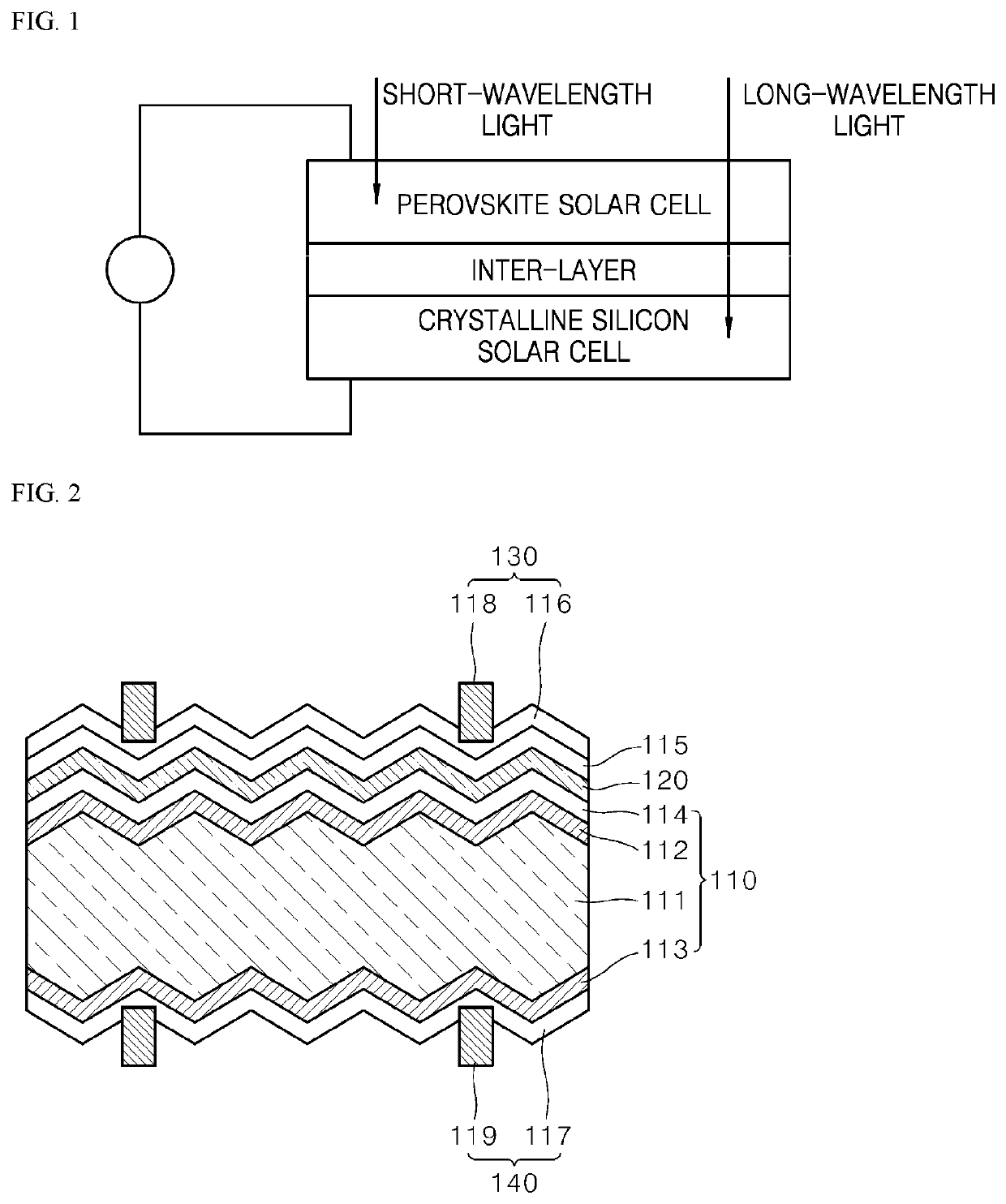
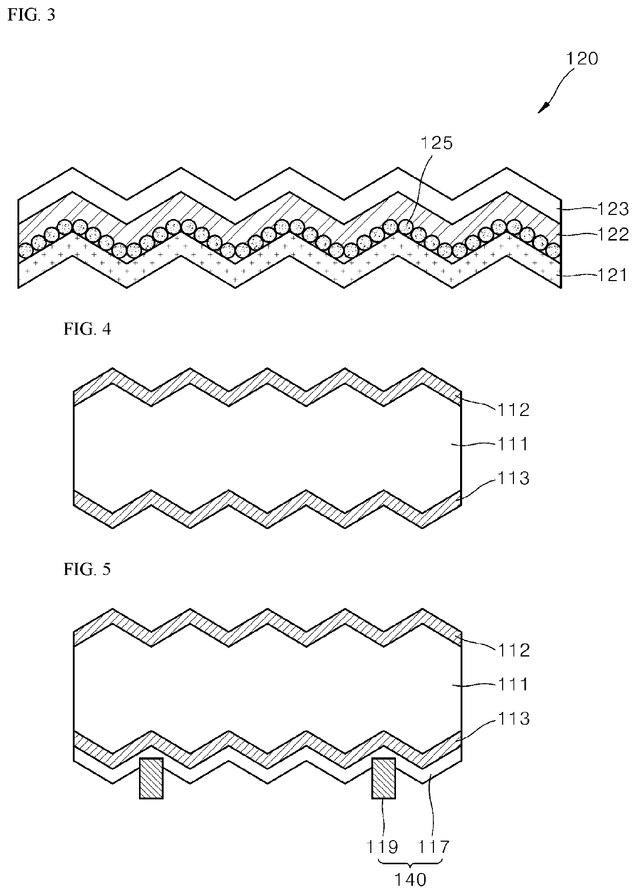
[0034]FIG. 2 is a cross-sectional view of a tandem solar cell according to one embodiment of the present disclosure, and FIG. 3 is a detailed cross-sectional view of the perovskite solar cell of FIG. 2.

[0035]Referring to FIGS. 2 and 3, a tandem solar cell 100 according to a first embodiment of the present disclosure has a structure of a two-terminal tandem solar cell in which a perovskite solar cell 120, as a second solar cell including an absorption layer having a relatively large ba...


PUM

PropertyMeasurementUnit
temperatureaaaaaaaaaa
thicknessaaaaaaaaaa
energy band gapaaaaaaaaaa

Abstract

The present disclosure relates to a method for manufacturing a monolithic tandem solar cell in which a perovskite solar cell is laminated and bonded on a silicon solar cell. According to the present disclosure, a first microporous precursor thin film is formed through a sputtering method on a substrate having an unevenly structured texture and then a halide thin film is formed on the first microporous precursor thin film to form a perovskite absorption layer, whereby light reflectance can be reduced and a path of light can be increased, and accordingly a light absorption rate can be increased.

Description

BACKGROUND1. Technical Field[0001]The present disclosure relates to a method of manufacturing a monolithic tandem solar cell in which a perovskite solar cell is stacked on and bonded to a silicon solar cell.2. Description of the Related Art[0002]Crystalline silicon (c-Si) solar cells are representative single-junction solar cells which are currently widely used as commercial solar cells. However, due to the low photoelectric conversion efficiency of crystalline silicon solar cells, the development of a tandem solar cell which is constructed by connecting two single-junction solar cells having absorption layers of different band gaps is actively ongoing.[0003]FIG. 1 is a schematic cross-sectional view of a two-terminal tandem solar cell, which is a common type of tandem solar cell.[0004]Referring to FIG. 1, in the solar cell, a single-junction solar cell including an absorption layer having a relatively large band gap and a single-junction solar cell including an absorption layer hav...

Claims


Application Information

Patent Timeline
Patent Type & Authority Applications(United States)
IPC IPC(8): H01L31/0725H01L31/0368H01L31/0224H01L31/0236H01L31/0392
CPCH01L31/022433H01L31/03685H01L31/02366H01L31/0392H01L31/022466H01L31/0725Y02P70/50Y02E10/545Y02E10/548H01L31/02363H01L31/0687H01L31/186H01L31/043Y02E10/544Y02E10/549H10K30/40H10K85/50H10K39/15
Inventor KIM, SEONGTAKAHN, SEH-WON
Owner SHANGRAO JINKO SOLAR TECH DEV CO LTD
Why Eureka
Try Eureka