Linkage lock

a technology of linkage lock and lock plate, which is applied in the field of linkage lock, can solve the problems that the above-mentioned prior arts still have room to improve, and achieve the effect of exquisite appearance and small folded siz

Active Publication Date: 2012-11-06
SINOX CO LTD
View PDF14 Cites 15 Cited by
  • Summary
  • Abstract
  • Description
  • Claims
  • Application Information

AI Technical Summary

Benefits of technology

[0006]The primary objective of the present invention is to provide a linkage lock having small folded size, particularly a linkage lock having exquisite appearance when folded.
[0012]Thereby, the linkage lock of the present invention not only has a small folded size but also has a novel appearance when folded.

Problems solved by technology

However, the abovementioned prior arts still have room to improve.

Method used


Image

  • Linkage lock
  • Linkage lock
  • Linkage lock

Examples


Embodiment Construction

[0026]The technical contents of the present invention are demonstrated with embodiments below.

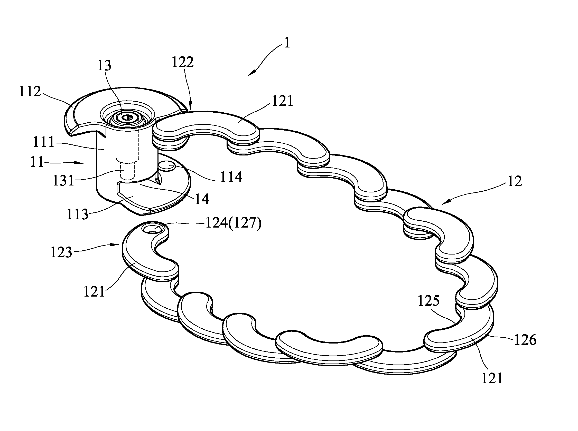
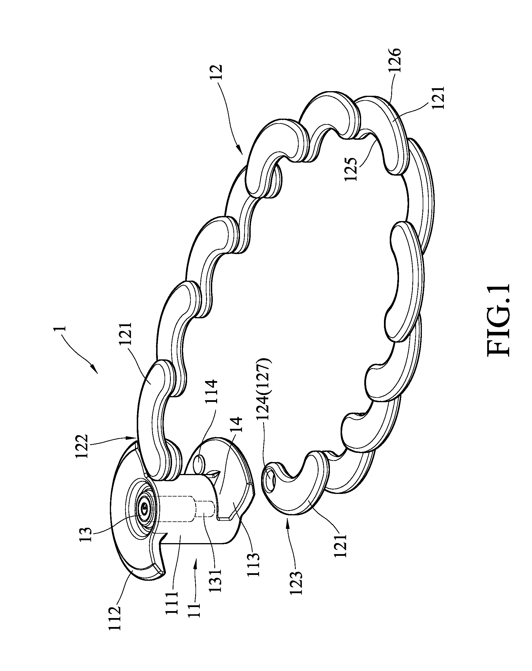
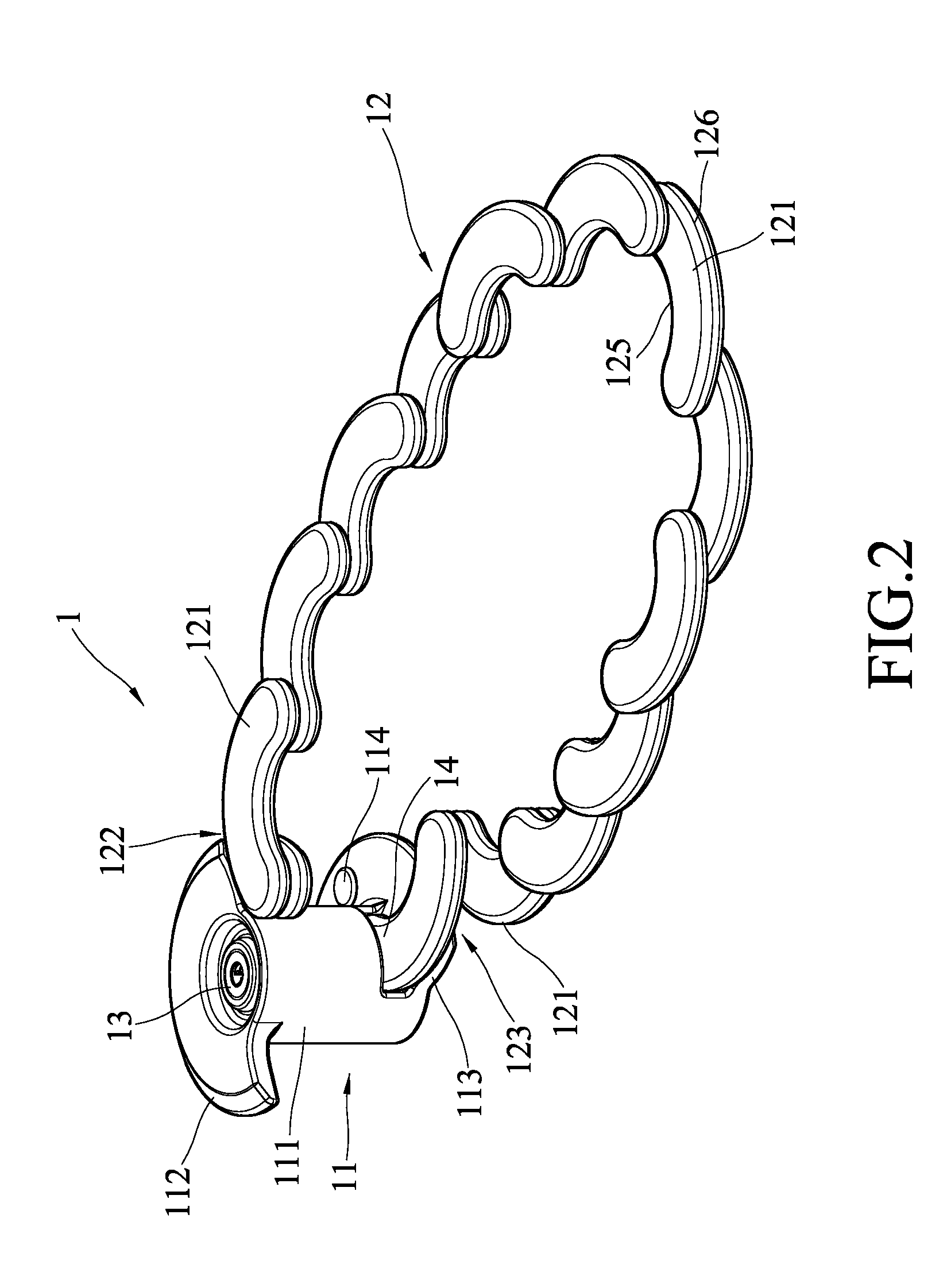
[0027]Refer to FIG. 1. The linkage lock 1 of the present invention comprises a lock body 11, a linkage chain 12 and a lock mechanism 13 arranged in the lock body 11. The lock body 11 has a shaft 111. The lock body 11 also has a first end cover 112 and a second end cover 113 respectively arranged at two ends of the shaft 111. The lock body 11 also has a socket 14 at a position where the second end cover 113 is joined with the shaft 111.

[0028]The linkage chain 12 is formed via linking a plurality of link plates 121. In one embodiment, the link plates 121 are pivotally linked one after one and one over one. The length of the linkage chain 12 depends on the length of each link plate 121 and the number of the link plates 121. The linkage chain 12 has a first end 122 and a second end 123. The first end 122 is joined to the lower side of the first end cover 112 of the lock body 11. The second end ...


PUM


Abstract

A linkage lock comprises a lock body, a linkage chain, and a lock mechanism arranged in the lock body. The linkage chain is formed via linking a plurality of link plates and has a first end joined with the lock body and a second end able to be inserted into and secured to a socket of the lock body. The lock body has a shaft. When intending to collect the linkage lock whose second end is unlocked, the user winds the linkage chain around the surface of the shaft with the shaft being a central axis to fold the linkage lock.

Description

BACKGROUND OF THE INVENTION[0001]1. Field of the Invention[0002]The present invention relates to a linkage lock comprising a lock body and a linkage chain wound around the lock body to reduce the volume of the lock.[0003]2. Description of the Related Art[0004]A U.S. Pat. No. 7,712,339 disclosed a joint rod lock, which comprises a lock body and a joint bar hoop formed via linking a plurality of bars, and which can be folded together to reduce the volume thereof when collected. A Taiwan patent No. M350495 also disclosed a similar lock.[0005]Compared with the conventional U-shape padlocks having a bulky volume, the abovementioned linkage locks indeed have reduced size. However, the abovementioned prior arts still have room to improve. For example, the appearance of the collapsed locks should be taken in consideration in design in addition to volume reduction.SUMMARY OF THE INVENTION[0006]The primary objective of the present invention is to provide a linkage lock having small folded siz...

Claims


Application Information

Patent Timeline
Patent Type & Authority Patents(United States)
IPC IPC(8): E05B67/06
CPCE05B67/003Y10T70/483Y10T70/491Y10T70/40Y10T70/409Y10T70/435Y10T70/5009Y10T70/5872
Inventor CHEUNG, MEI LING
Owner SINOX CO LTD
Why Eureka
Try Eureka