Locking pliers with retractable pivotal movable jaw

a technology of pivotal movable jaw and locking pliers, which is applied in the field of locking pliers, can solve the problems of inconvenience in storage and transportation, unattractive visual appearance, and a large number of conventional locking pliers

Active Publication Date: 2012-11-06
SHIH SHIN AN
View PDF4 Cites 13 Cited by
  • Summary
  • Abstract
  • Description
  • Claims
  • Application Information

AI Technical Summary

Problems solved by technology

However, the conventional locking pliers suffer from a number of disadvantages.
For example, the slide bar 4 can cause inconvenience in storage and transportation.
Moreover, it is visually unattractive.
Further, it is not suitable to be used in areas to which access is difficult or in which there is limited clearance.

Method used


Image

  • Locking pliers with retractable pivotal movable jaw
  • Locking pliers with retractable pivotal movable jaw
  • Locking pliers with retractable pivotal movable jaw

Examples


Embodiment Construction

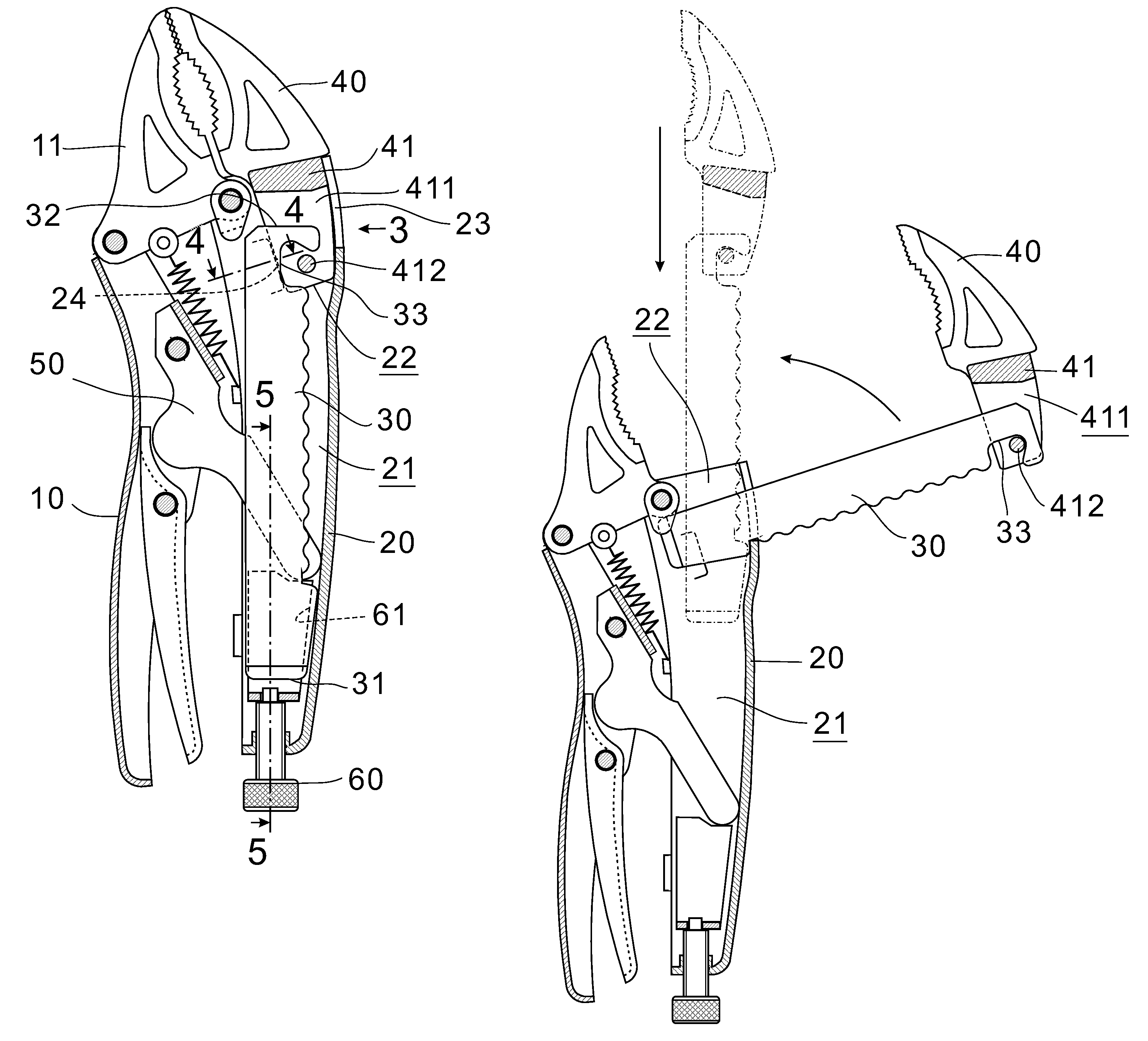
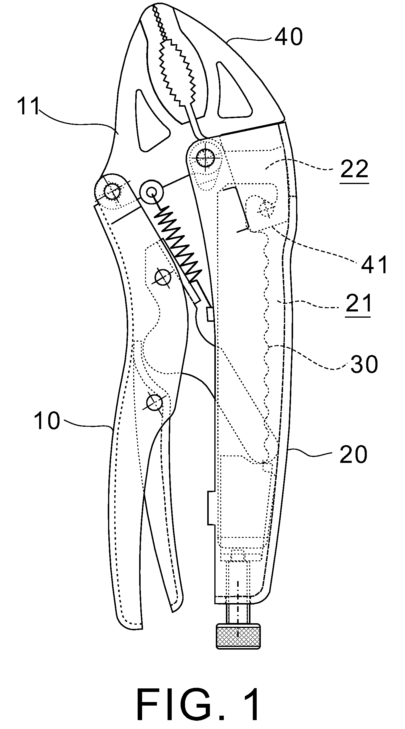
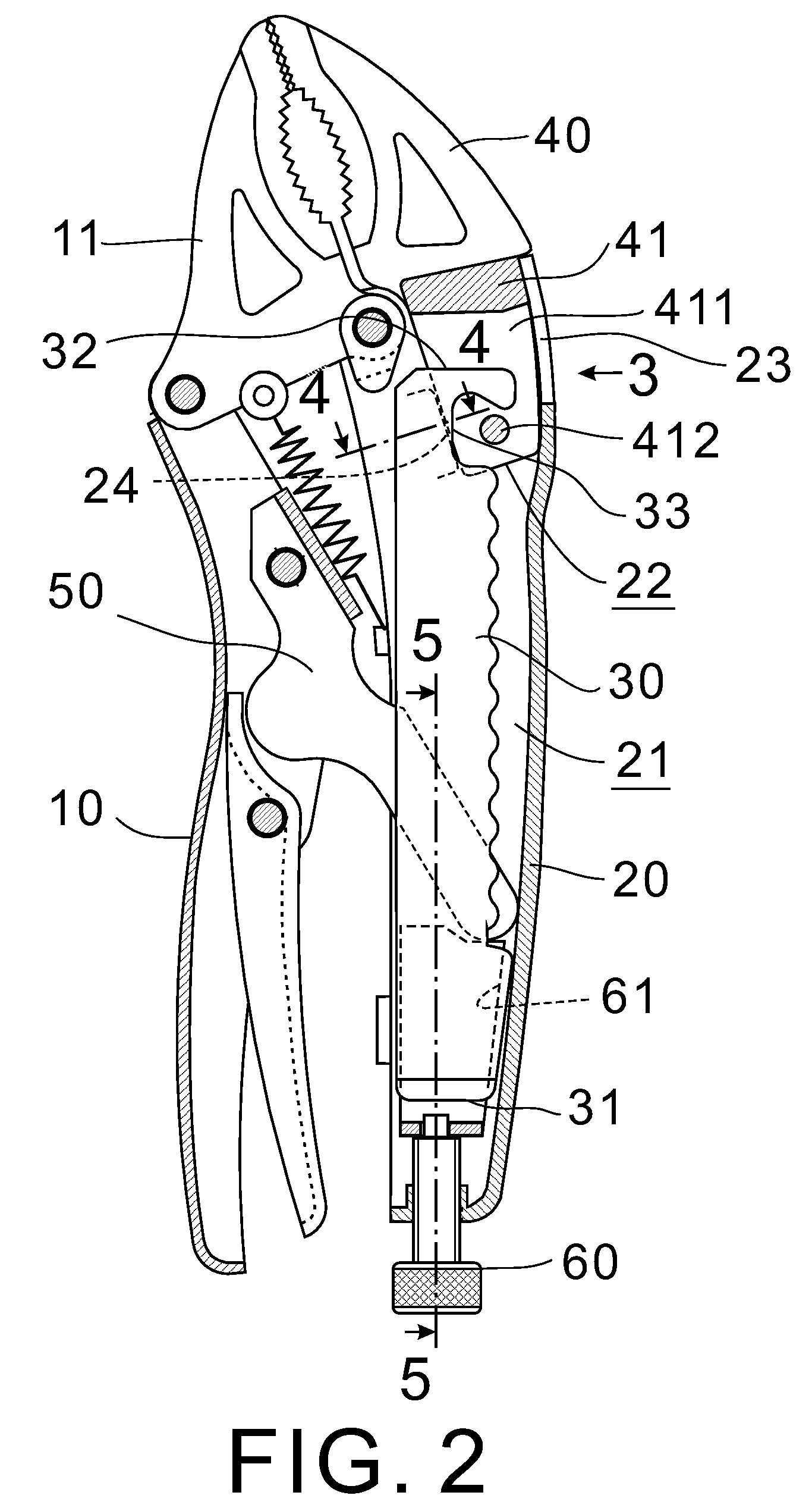
[0021]Referring to FIGS. 1 to 9, a pair of locking pliers in accordance a first preferred embodiment of with the invention is shown.

[0022]The locking pliers comprises a hollow first handle unit 10, a substantially triangular stationary jaw 11 having one rear end pivotably secured to a forward end of the first handle unit 10, a second handle unit 20 pivotably secured to the other rear end of the stationary jaw 11, a movable jaw 40 at a forward end of the second handle unit 20, a spring loaded, pivotal locking unit 50 interconnected between the first and second handle units 10, 20, a slide bar 30 mounted in a hollow 21 of the second handle unit 20 (also partially in the hollow of the locking unit 50 as shown in FIG. 5), and an adjustment screw 60 extending rearward of the second handle unit 20, the adjustment screw 60 being adapted to adjust the spacing of the jaws 11, 40 by threading. The adjustment screw 60 has a U-shaped member 61 at its forward end. The U-shaped member 61 has a fo...


PUM


Abstract

A locking pliers includes a slide bar mounted in both second handle unit and locking unit and comprising a wavy edge facing bottom of the second handle unit, the wavy edge including a rear slot member and a forward hook; and a movable jaw at a forward end of the second handle unit and comprising two intermediate opposite stop members each having an inclined edge, a channel between the stop members with a forward end of the slide bar movably received therein, and a rear stop bar interconnected two sidewalls of a rear portion of the movable jaw, the inclined edges being stopped by bending members on sidewalls of the second handle unit for retaining the stop members in an inoperative position.

Description

BACKGROUND OF THE INVENTION[0001]1. Field of Invention[0002]The invention relates to locking pliers and more particularly to a pair of locking pliers with improved characteristics.[0003]2. Description of Related Art[0004]A pair of typical locking pliers is shown in FIG. 11 and comprises a first handle unit 1, a stationary jaw 3 pivotably secured to the first handle unit 1, a second handle unit 2 pivotably secured to the stationary jaw 3, a slide bar 4 extending outwardly laterally from a forward end of the second handle unit 2, a movable jaw 5 slidably mounted on the slide bar 4, and a self-adjusting locking unit (not numbered) interconnected between the first and second handle units 1, 2.[0005]In use, the jaws 3, 5 are opened a sufficient distance by sliding the movable jaw 5 along the slide bar 4. Next, an object is placed between the jaws 3, 5. Next, squeeze the first and second handle units 1, 2 together to lock the jaws 3, 5 onto the gripped object.[0006]However, the convention...

Claims


Application Information

Patent Timeline
Patent Type & Authority Patents(United States)
IPC IPC(8): B25B7/12
CPCB25B5/127B25B7/123
Inventor SHIH, SHIN-AN
Owner SHIH SHIN AN
Why Eureka
Try Eureka