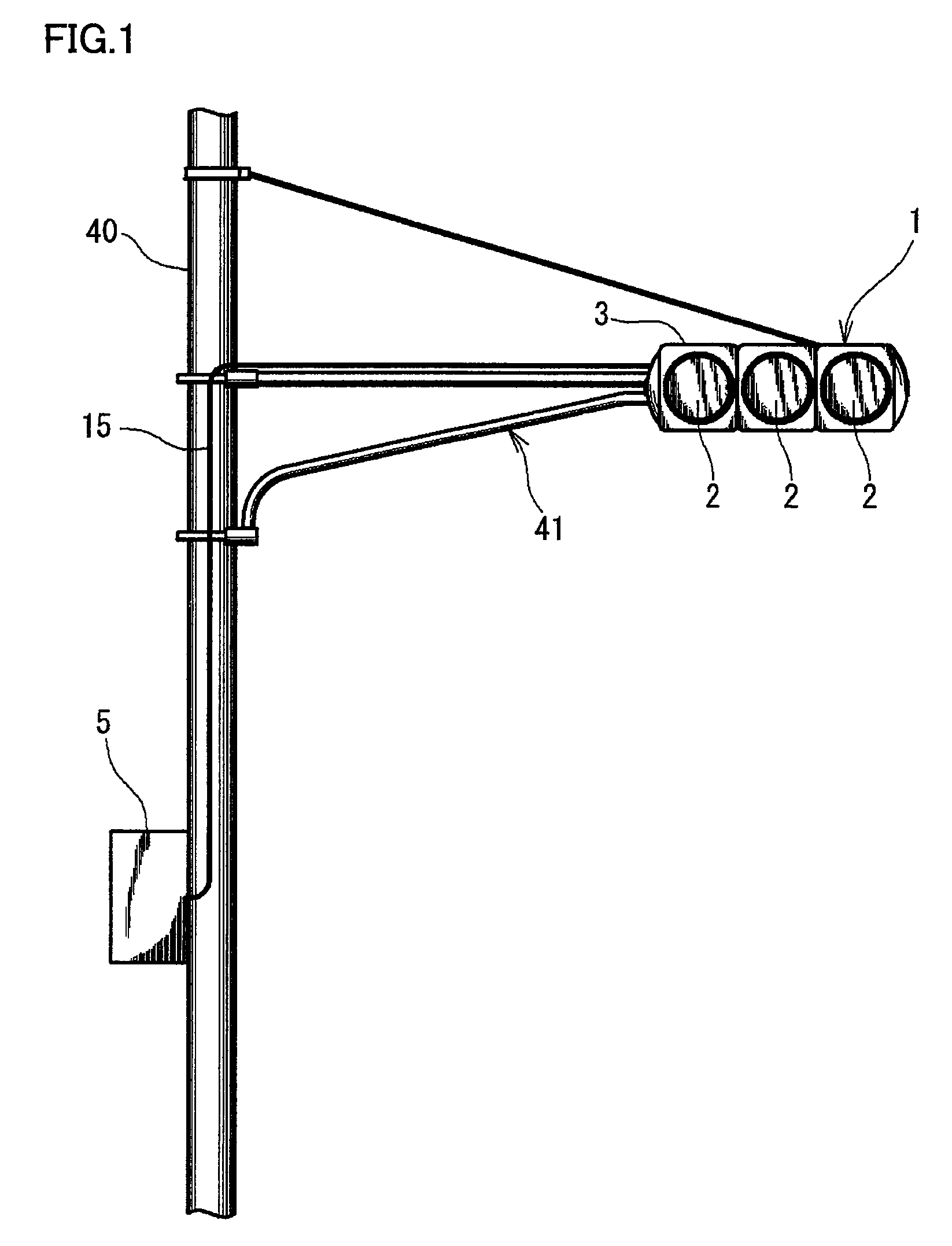
Lamp apparatus, antenna unit for lamp apparatus, communication system, and traffic signal controller
a technology for lamps and lamps, applied in the field of lamps, can solve the problems of not being economical to install a new pole just for the antenna, not being preferable, etc., and achieve the effect of avoiding spoiling the aesthetic preference of the road
- Summary
- Abstract
- Description
- Claims
- Application Information
AI Technical Summary
Benefits of technology
Problems solved by technology
Method used
Image
Examples
first embodiment
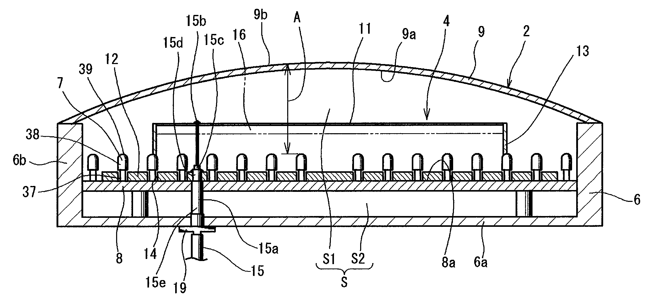
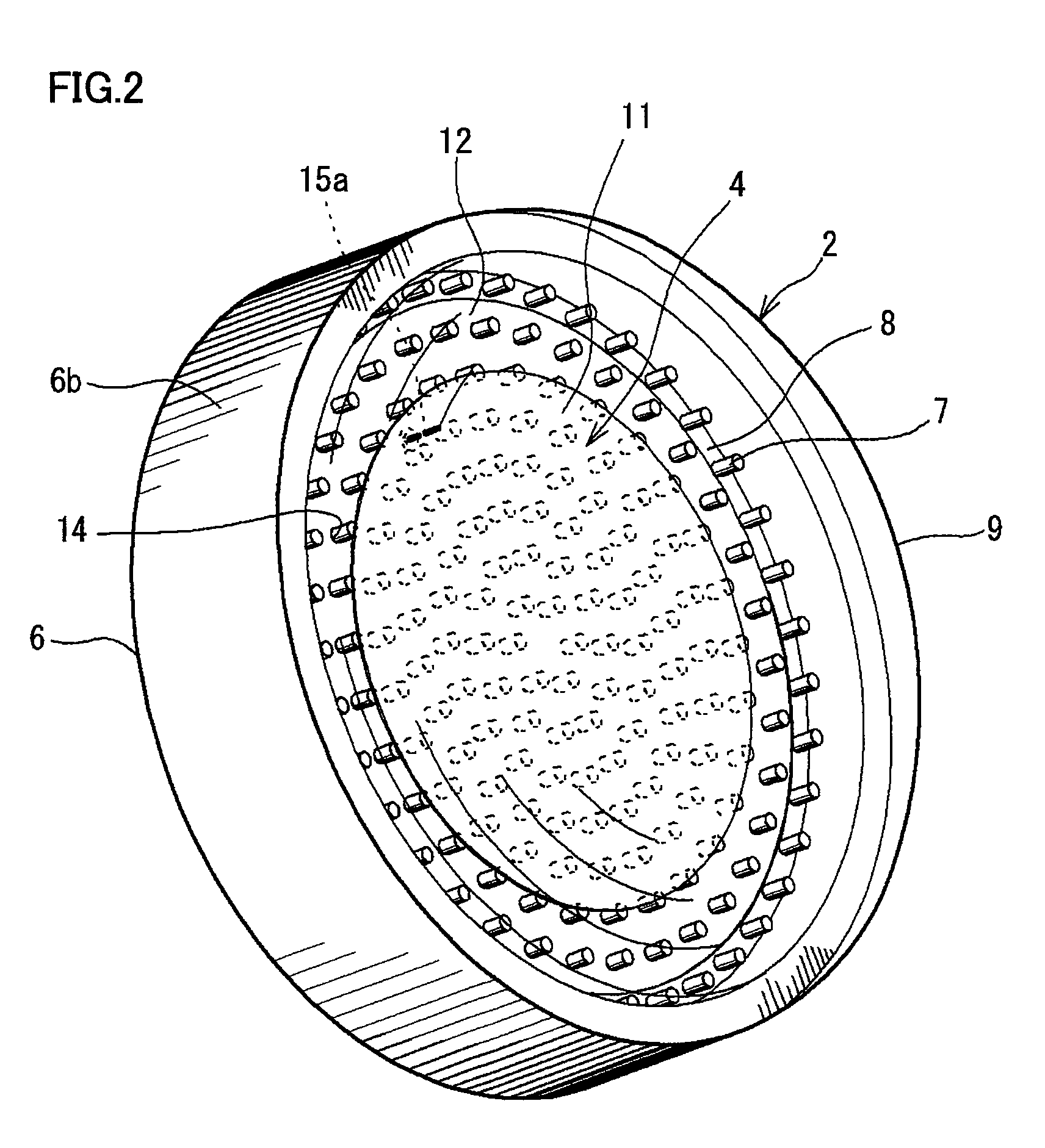
[0091]FIGS. 2, 3 and 4 are a perspective view, front view, and cross sectional view, respectively, of one optical unit 2 (First Embodiment). Optical unit 2 includes a light emitting diode 7 (hereinafter, LED) as the light emitter, a substrate 8 having a plurality of LEDs 7 mounted on a front face 8a, a storage member 6, and a cover member 9. Substrate 8 has a wiring pattern formed at the backside, and is connected to a terminal 37 of LED 7. A plurality of LEDs 7 are arranged on substrate 8, spread in planar manner. LED 7 includes a lens unit 38 in which an LED element (not shown) is provided.
[0092]Storage member 6 is dish-shaped, and opened facing the front side, including a bottom (bottom wall) 6a, and a side (sidewall) 6b upright from the circumferential edge of bottom 6a. Cover member 9 is attached at the front of storage member 6 corresponding to the opening side. A storage cavity S is defined between storage member 6 and cover member 9. LED 7 and substrate 8 are accommodated in...
second embodiment
[0126]Another embodiment (Second Embodiment) of an antenna-embedded signal lamp apparatus having antenna 4 incorporated in an optical unit 2 will be described. FIG. 8 is a sectional view of optical unit 2 and antenna 4 incorporated in the signal lamp apparatus. Likewise with the previous embodiment, the signal lamp apparatus includes optical unit 2 and antenna 4. Optical unit 2 includes substrate 8 having LEDs 7 mounted, and a cover member 9 of visible-light transmittance, spread over LEDs 7 at the front. Antenna 4 includes patch element 11 situated in a range A from cover member 9 up to leading end 39 of LED 7, and ground element 12 at the rear of patch element 11. Patch element 11 has visible-light transmittance.
[0127]The difference between the embodiment of FIG. 8 and the previous embodiment (FIG. 4) lies in the attachment of patch element 11. The remaining configuration is similar. Patch element 11 is formed at a rear face 9a of cover member 9. In other words, patch element 11 i...
third embodiment
[0128]Another embodiment (Third Embodiment) of an antenna-embedded signal lamp apparatus will be described. FIG. 9 is a sectional view of optical unit 2 and antenna 4 incorporated in the signal lamp apparatus. The difference between the embodiment of FIG. 9 and the prior embodiment (FIG. 4) lies in the attachment of patch element 11 and the location of ground element 12. The attachment of patch element 11 is identical to that shown in FIG. 8. Patch element 11 is formed at rear face 9a of cover member 9. Ground element 12 is provided frontward of leading end 39 of LED 7.
[0129]Ground element 12 has visible-light transmittance also in this case. Ground element 12 exhibits visible-light transmittance by taking a configuration similar to that of patch element 11. Namely, ground element 12 is constituted of a conductive body based on a mesh structure or contour frame structure. Ground element 12 is also constituted of a conductor membrane having visible-light transmittance.
[0130]Likewise ...
PUM
 Abstract
Description
Claims
Application Information
 - R&D
- Intellectual Property
- Life Sciences
- Materials
- Tech Scout
- Unparalleled Data Quality
- Higher Quality Content
- 60% Fewer Hallucinations
Browse by: Latest US Patents, China's latest patents, Technical Efficacy Thesaurus, Application Domain, Technology Topic, Popular Technical Reports.
© 2025 PatSnap. All rights reserved.Legal|Privacy policy|Modern Slavery Act Transparency Statement|Sitemap|About US| Contact US: help@patsnap.com


