Plastic fuel tank

a fuel tank and plastic technology, applied in the field of plastic or resinous fuel tanks, can solve the problems of degradation of ethylene/vinyl alcohol copolymer, and achieve the effects of reducing the cost of plastic fuel tanks, reducing the cost of recycled polyethylene materials, and eliminating concerns

Active Publication Date: 2012-11-27
HONDA MOTOR CO LTD
View PDF24 Cites 0 Cited by
  • Summary
  • Abstract
  • Description
  • Claims
  • Application Information

AI Technical Summary

Benefits of technology

[0006]It is therefore an object of the present invention to provide a plastic fuel tank that prevents fuel seepage and is weather resistant.
[0007]According to one aspect of the present invention, there is provided a plastic fuel tank including a tank assembly and a filler neck, comprising: an ethylene / vinyl alcohol layer for preventing fuel seepage; an outermost polyethylene layer laminated onto one surface of the ethylene / vinyl alcohol layer; an innermost polyethylene layer laminated onto another surface of the ethylene / vinyl alcohol layer; and the outermost polyethylene layer being a high-density polyethylene layer colored so as to minimize transmission of ultraviolet light.
[0008]The outermost polyethylene layer minimizes the transmission of ultraviolet light, enabling degradation of the ethylene / vinyl alcohol layer or the like to be prevented, and weather resistance to be improved. As a result, it is possible to provide a plastic fuel tank that prevents fuel seepage and is weather resistant.

Problems solved by technology

It is known that the ethylene / vinyl alcohol copolymer will degrade when exposed to ultraviolet light for a long period of time.

Method used


Image

  • Plastic fuel tank
  • Plastic fuel tank
  • Plastic fuel tank

Examples


Embodiment Construction

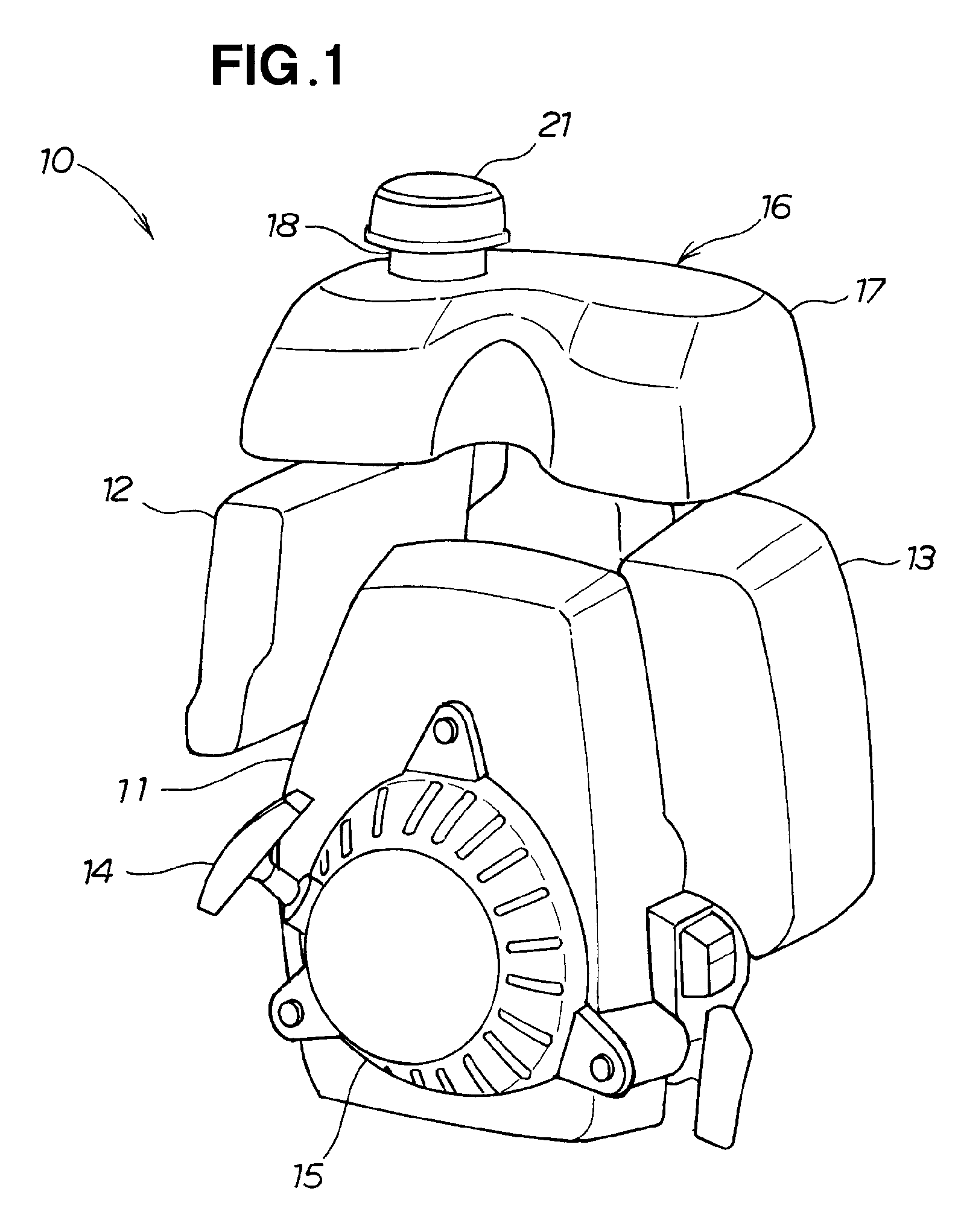
[0022]As shown in FIG. 1, a general-purpose engine 10 includes an engine assembly 11, a suction part 12 provided to a side part of the engine assembly 11 and used to draw outside air into the engine assembly 11, an exhaust part 13 provided to a side part of the engine assembly 11 and used to discharge exhaust from the engine assembly 11 to the exterior, a recoil starter 14 provided to a lower part of the engine assembly 11 and used to start up the engine assembly 11, and a recoil starter cover 15 for covering the recoil starter 14.

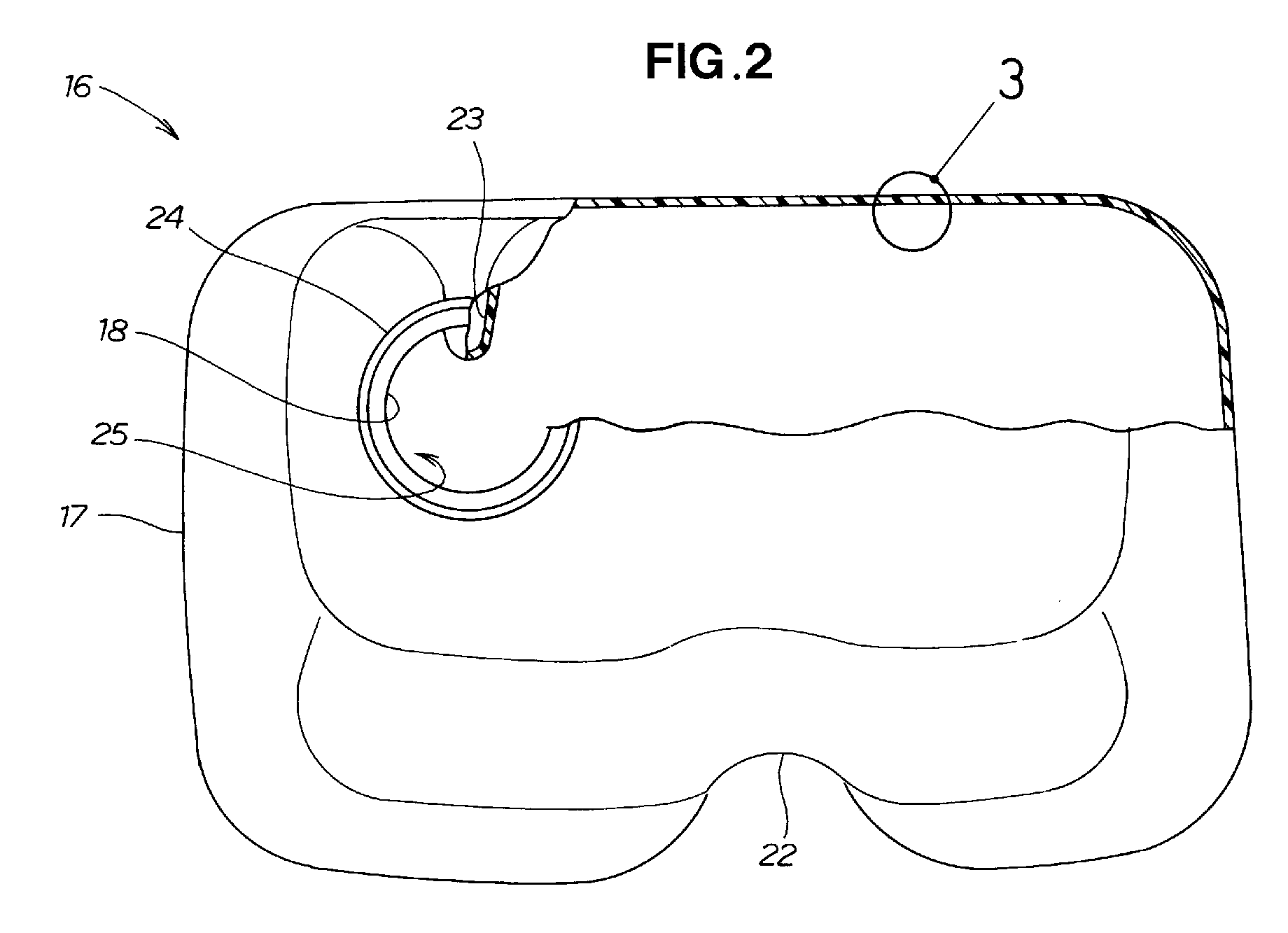
[0023]The general-purpose engine 10 is also provided with a plastic fuel tank 16 for storing fuel in the upper part of the engine assembly 11. The plastic fuel tank 16 includes a tank assembly 17 for storing fuel, a filler neck 18 molded integrally with the tank assembly 17 and used to introduce fuel, and a filler cap 21 mounted on the filler neck 18 and used to block the filler neck 18.

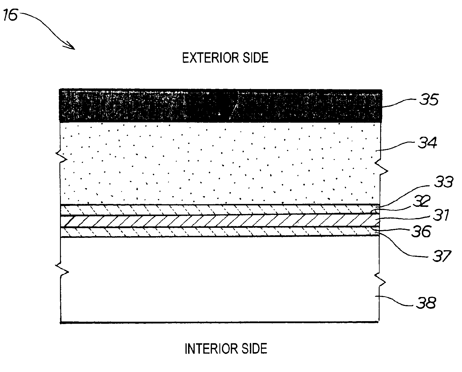
[0024]As shown in FIG. 2, the tank assembly 17 of the plastic fuel tan...


PUM

PropertyMeasurementUnit
densityaaaaaaaaaa
weather resistanceaaaaaaaaaa
transmissionaaaaaaaaaa

Abstract

A plastic fuel tank is disclosed including polyethylene layers laminated respectively onto an upper surface and a lower surface of an ethylene / vinyl alcohol layer for preventing fuel seepage. The outermost polyethylene layer laminated onto the upper surface is a high-density polyethylene layer colored black so as to minimize transmission of ultraviolet light.

Description

FIELD OF THE INVENTION[0001]The present invention relates to a plastic or resinous fuel tank wherein a polyethylene layer is laminated via an adhesive plastic layer onto both sides of an ethylene / vinyl alcohol layer for preventing fuel seepage or permeation.BACKGROUND OF THE INVENTION[0002]In recent years, plastic fuel tanks have also come to be used in general-purpose engines and the like, and known plastic fuel tanks offering a possible solution with respect to environmental pollution are disclosed, for example, in JP-A 2004-52659.[0003]FIG. 5 hereof shows the plastic fuel tank disclosed in JP-A 2004-52659.[0004]Referring to FIG. 5, a coupling member 102 is mounted on a tank assembly 101 in a plastic fuel tank 100. The tank assembly 101 includes a barrier layer 103 constructed from an ethylene / vinyl alcohol copolymer for preventing fuel seepage; an innermost layer 104 laminated onto an interior side of the barrier layer 103, and constructed from polyethylene; and an outermost laye...

Claims


Application Information

Patent Timeline
Patent Type & Authority Patents(United States)
IPC IPC(8): B29D22/00
CPCB32B1/02B32B27/32Y10T428/1352Y10T428/1383B32B7/12B32B27/08B32B27/20B32B27/306B32B2250/03B32B2250/40B32B2272/00B32B2307/40B32B2307/4026B32B2307/412B32B2307/712B32B2605/00
Inventor KOYAMA, KAZUTAKEYONEMURA, MASAHIROTABATA, YUTAKASAITOH, TERUYUKI
Owner HONDA MOTOR CO LTD
Why Eureka
Try Eureka