

Plastic fuel tank
a fuel tank and plastic technology, applied in the direction of fuel supply, thin material processing, packaging, etc., can solve the problems of ethylene/vinyl alcohol copolymer deformation, and achieve the effects of reducing the cost of plastic fuel tanks, reducing waste, and reducing was
- Summary
- Abstract
- Description
- Claims
- Application Information
AI Technical Summary
Benefits of technology
Problems solved by technology
Method used
Image

Examples
Embodiment Construction
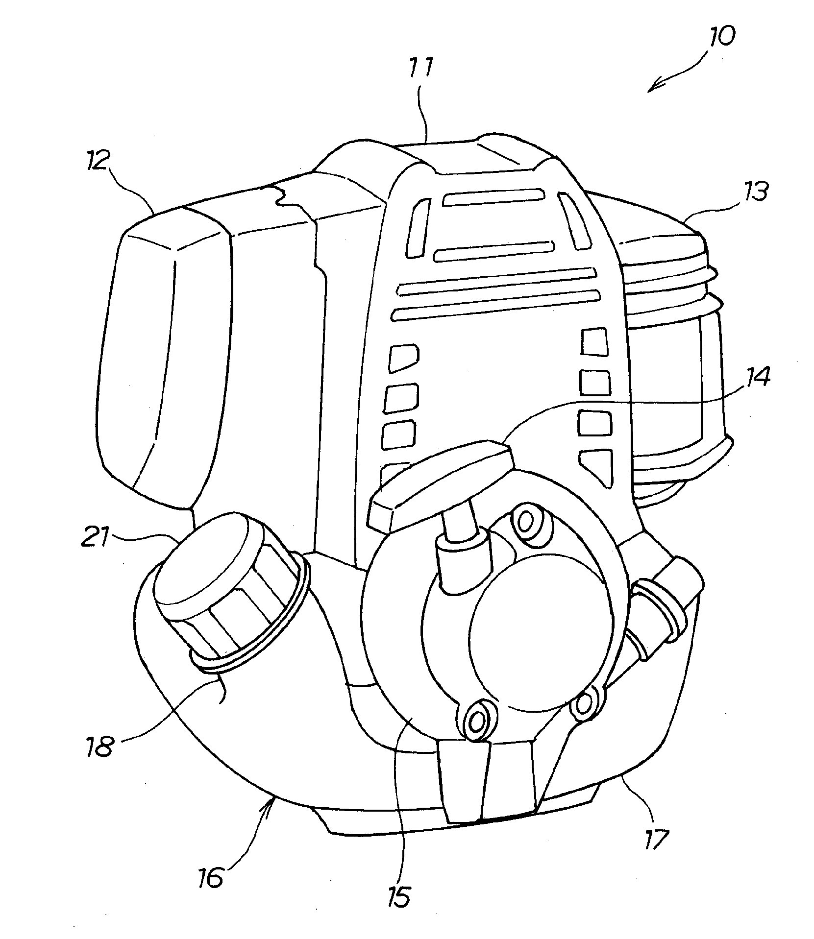
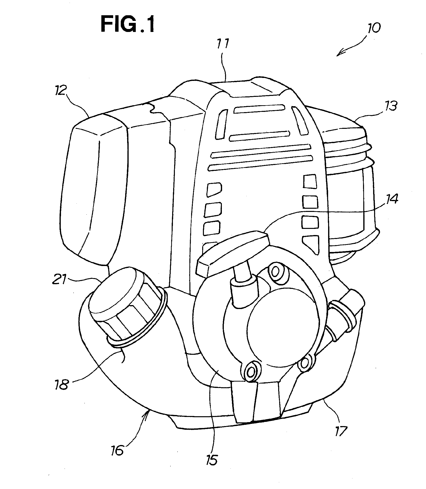
[0025]As shown in FIG. 1, a general-purpose engine 10 includes an engine assembly 11, a suction part 12 provided to a side part of the engine assembly 11 and used to draw outside air into the engine assembly 11, an exhaust part 13 provided to a side part of the engine assembly 11 and used to discharge exhaust from the engine assembly 11 to the exterior, a recoil starter 14 provided to a lower part of the engine assembly 11 and used to start up the engine assembly 11, and a recoil starter cover 15 for covering the recoil starter 14.
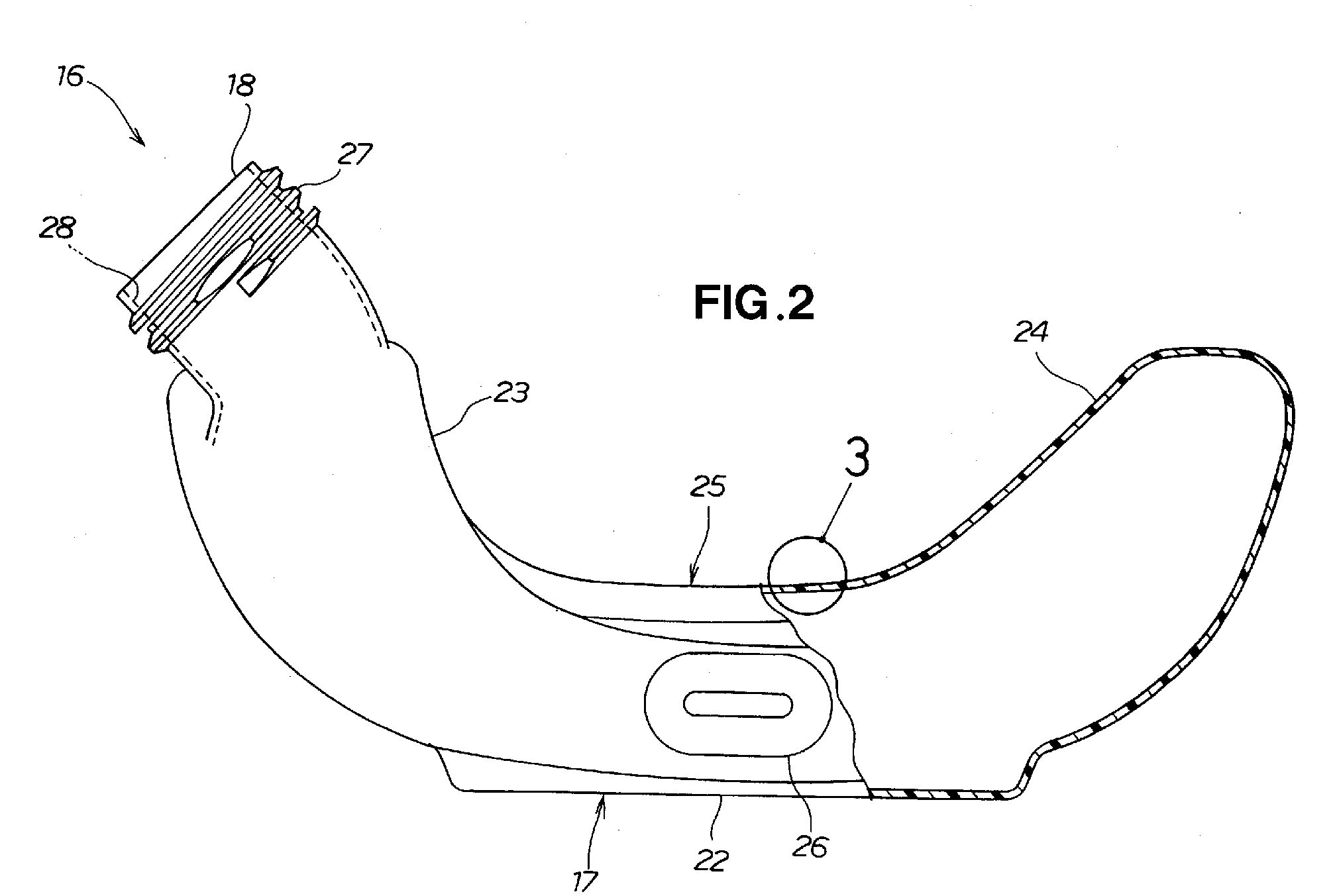
[0026]The general-purpose engine 10 is also provided with a plastic fuel tank 16 for storing fuel in the lower part of the engine assembly 11. The plastic fuel tank 16 includes a tank assembly 17 for storing fuel, a filler neck 18 molded integrally with the tank assembly 17 and used to introduce fuel, and a filler cap 21 mounted on the filler neck 18 and used to block the filler neck 18.
[0027]As shown in FIG. 2, the tank assembly 17 of the plastic fuel tan...
PUM
 Abstract
Description
Claims
Application Information