Cut valve

a technology of cutting valves and cylinders, applied in the field of cutting valves, can solve the problem of not being able to completely prevent the leakage of fuel to the vapor pipe side, and achieve the effect of preventing the leakage of fuel, and reducing the amount of fuel accumulated in the gap

Inactive Publication Date: 2006-07-27
PIOLAX CO LTD
View PDF15 Cites 0 Cited by
  • Summary
  • Abstract
  • Description
  • Claims
  • Application Information

AI Technical Summary

Benefits of technology

[0019] According to the above-described fourth aspect of the invention, since the aforementioned interval is set to 2 to 3 mm, the amount of fuel accumulated in that gap can be made small, and it is possible to effectively prevent the fuel from leaking to the outside when the float valve opens. When the fuel dropped, the float valve can be made to move quickly away from the ceiling portion of the housing.
[0020] According to the cut valve of the invention, in cases such as where the fuel in the fuel tank has tilted, the fuel level rises, and the float valve floats up and abuts against the valve seat to close the vent hole, thereby preventing the fuel leakage. Also, at least one of the float valve and a portion of the housing with which the float valve comes into contact during its sliding is formed of a resin material of a sliding grade. Therefore, the coefficient of friction is small, the float valve slides smoothly, and even in the case where the fuel tilts greatly, the opening and closing operation of the vent passage between the interior of the fuel tank and the outside can be effected reliably. In addition, since at least one of the relevant parts is formed of a resin material of a sliding grade, the wear resistance improves, and even in the case where the cut valve is used for long periods of time, it is possible to suppress a decline in the sealability between the float valve and the valve seat. In addition, since the inner periphery of the valve seat has a tapered shape in which its diameter is gradually enlarged in the direction toward the opening at an angle of 31 to 34 degrees with respect to the axis of the vent hole, the float valve is made not difficult to come off the inner periphery of the valve seat, and the float valve comes into contact with the inner periphery of the valve seat with an appropriate contact area. Therefore, it becomes possible to sufficiently ensure the sealability between the float valve and the valve seat.

Problems solved by technology

However, with the above-described conventional cut valve, if the vehicle makes a quick turn, tilts greatly, is rolled over, or travels on a road surface having large irregularity, the fuel in the fuel tank sways greatly, so that the float is unable to follow the swaying motion of the fuel, making it impossible to completely prevent the leakage of fuel to the vapor pipe side through the vent passage.

Method used


Image

  • Cut valve
  • Cut valve
  • Cut valve

Examples


example

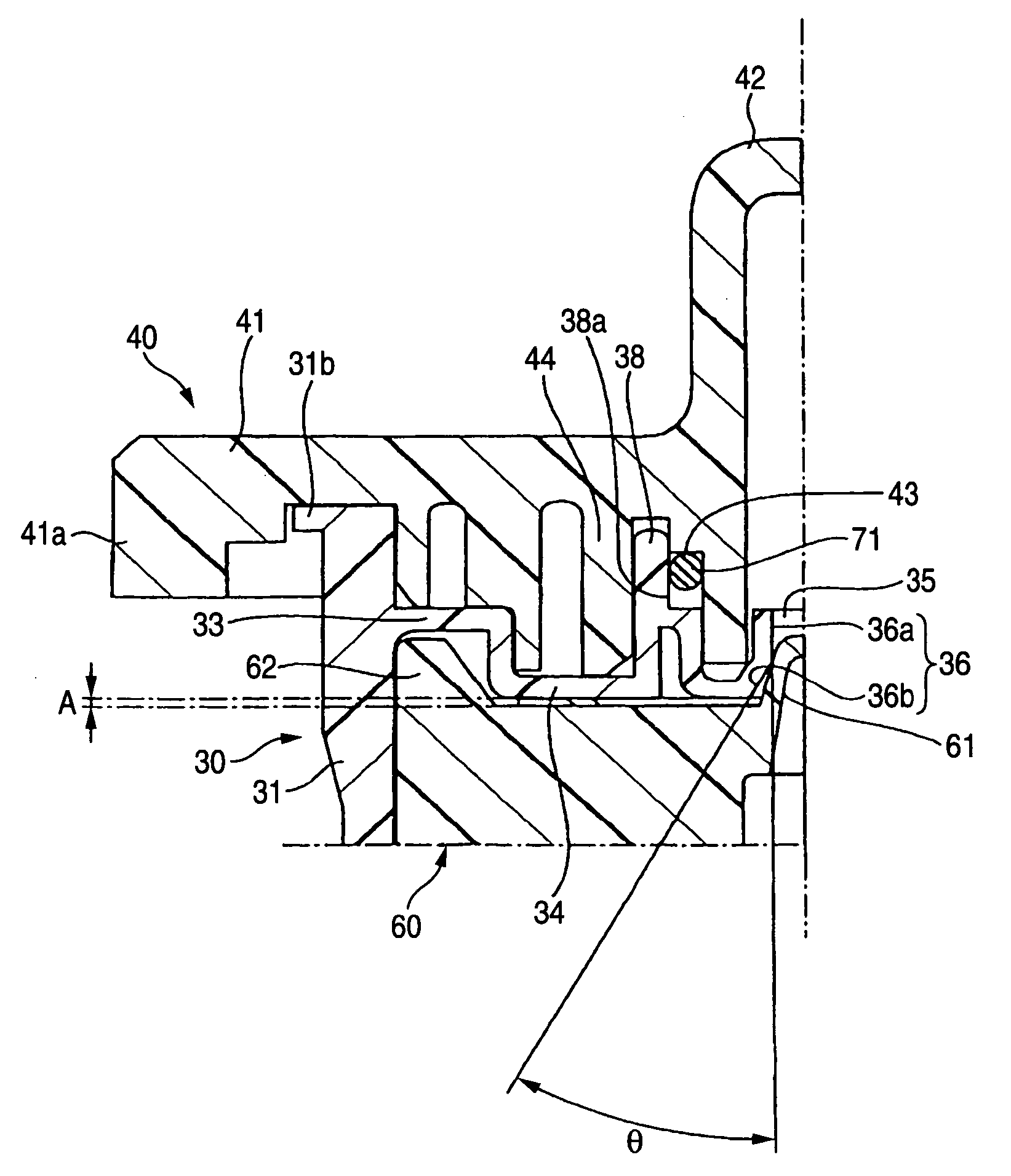
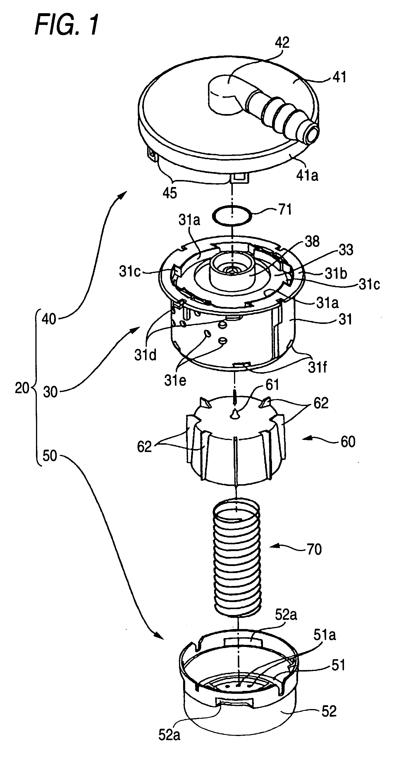
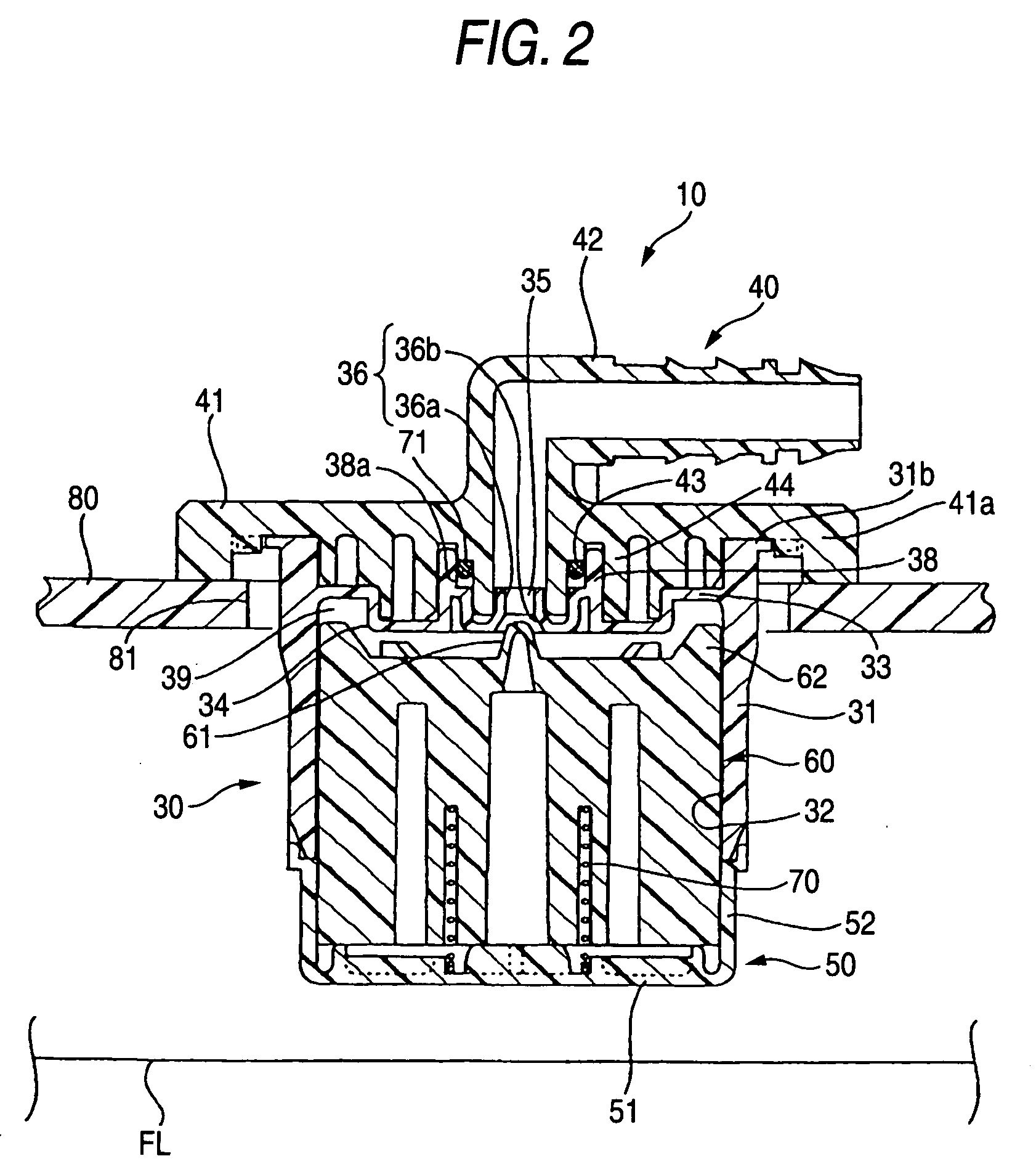
[0065] The cut valve shown in FIG. 1 was fabricated. At that juncture, the tubular body 30 was formed by using a polyoxymethylene (POM) based resin material of a sliding grade. Further, the seal portion 36b of the valve seat 36 was formed with an angle θ of 33.5° with respect to the axis of the vent hole 35 of the tubular body 30. In addition, the cover 40 was formed of polyethylene, and the float valve 60 and the bottom portion 50 were formed of ordinary polyoxymethylene (POM) which was not a sliding grade. It should be noted that the interval A between the upper surface of the float valve 60 and the protruding portion 34 of the tubular body 30 was 2.4 mm when the vent hole 35 was closed by abutting the head 61 against the seal portion 36b of the valve seat 36.


PUM


Abstract

A cut valve which is installed on a fuel tank and is adapted to shut off a vent passage between the interior of the fuel tank and the outside when a fuel level in the fuel tank has risen, including: a housing having: a cover having a lead-out pipe connected to an external pipe; a tubular body having a vent hole communicating with the lead-out pipe; and a bottom portion closing a lower surface of the tubular body; and a float valve which is adapted to open or close the vent hole by coming into contact with and moving away from a valve seat provided at a peripheral edge of the vent hole in the ceiling portion, wherein an inner periphery of the valve seat has a tapered shape in which its diameter is gradually enlarged in a direction toward the float valve.

Description

BACKGROUND OF THE INVENTION [0001] 1. Field of the Invention [0002] The present invention relates to a cut valve which is installed on a fuel tank of an automobile or the like and is adapted to shut off a vent passage between the interior of the fuel tank and the outside when the fuel level in the fuel tank has risen, so as to prevent leakage to the outside. [0003] 2. Description of the Related Art [0004] A fuel tank of an automobile is provided with a fuel vapor pipe for discharging fuel vapor to a canister through a cut valve and a check valve when the internal pressure has exceeded a predetermined value. The cut valve is provided to prevent the fuel in the fuel tank from leaking to the outside through the fuel vapor pipe when the automobile turned or tilted. Namely, the cut valve has a float valve in its interior, and when the fuel level has risen, the float valve is adapted to rise to shut off a vent passage communicating with the fuel vapor pipe. [0005] Japanese Patent No. 2972...

Claims


Application Information

Patent Timeline
Patent Type & Authority Applications(United States)
IPC IPC(8): F16K24/04
CPCF16K24/044Y10T137/0874Y10T137/3099B60K15/01
Inventor FURUYA, MASASHIMATSUO, SHINICHI
Owner PIOLAX CO LTD
Why Eureka
Try Eureka